I bought the R32 knowing that with the mileage it had I should be expecting it to need the timing chain guides
and dual mass flywheel (DMF) replaced at any time. The timing chains on the VR6 are a lifetime part, but the
tensioners and guides are not. The chains themselves are inexpensive enough that most people go ahead and replace
them too, while they're in there. It is a substantial amount of work to get access to both the upper and lower
chains, in order to replace the guides and tensioners, and since the chains are on the PTO side of the engine,
if it's anywhere close to possibly needing the DMF replaced, that's the time to do it, since you'll need to
remove it to get access to the lower timing chain. Likewise, if you're in there doing the DMF it makes sense
to do the timing chains while you're in there. I started hearing the tell-tale worn DMF noises last winter, as
well as feeling the engine sometimes shake at idle (especially on cold starts). The DMF is two parts, with the
inner and outer parts being connected via strong springs, similar to a sprung clutch disc. The more worn the DMF
springs get, the more it is mechanically allowed to run out of true, throwing its balance off under certain conditions.
Catastrophic DMF failures have been known to lead to engine crank case and transmission bell housing damage. Folks
with the traditional manual transmissions have the option of reverting to the older style single mass flywheel, which
is not prone to these issues (worst case, you have it resurfaced if it has really been abused). The DMF, with it's
soft "sprung" connection, helps to eliminate jerkiness during sloppy or careless shifting. There is no real need for
the DMF with a regular manual transmission, but this is not the case with the DSG transmissions. In order for them
to function properly without becoming quickly damaged, it needs that extra bit of slop allowed by the DMF. The two
clutch packs used by the DSG are your typical wet clutches, inside the transmission, so there is no sprung clutch
disc to help dampen slight mismatches in engine and transmission speed during shifts.
Back to the story at hand, I found myself needing to do the DMF and knowing that the timing chains guides and
tensioners would be due soon as well. I went ahead and ordered everything I needed to replace the chains themselves
as well as all guides and tensioners, the DMF, and also oil and filter for the DSG transmission. Don't forget, as I did,
that to access the lower timing chain you will need to remove the rear main seal housing and so the rear main seal should
be replaced at the same time. I had to make a run to the dealership at the last minute, to pick up a new seal for a
not-so-great price. You will also need some of that good VW/Audi gasket maker for sealing around the timing chain covers,
in addition to the round seals for the variable valve timing connectors that go through the upper timing cover. Get
a new axle bolt, because you'll be removing the driver's side axle completely. Also, new subframe mounting bolts
(look at the updated ones sold by ECS Tuning, to replace the stock stretch bolts), and unless you want to pay for an
alignment after work is completed you'll want to get the special tools for maintaining the subframe-to-body alignment.
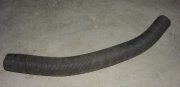
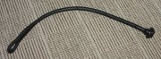
You don't need the special VW tools for clamping the coolant hoses shut, just get yourself a few pairs of regular coolant
hose clamps, or even use vise grips with something to protect the hoses from the serrated jaws. Bear in mind also, that
you will be removing the intake manifold and valve cover... so all of those gaskets are recommended unless they're pretty
new already. Lastly, don't forget the flywheel bolts (there are 10 of them) - they are not reusable and for the price versus how much work it
takes to get to them and the amount of damage that could result if they fail, why take the chance? If you don't already
have a set of the male 12 point sockets ("triple square" bits), you'll be needing to get them too. A cam locking tool
is absolutely necessary, but you do not need to buy the official one. A piece of steel plate, about 5/32" (4mm) thick
that is long enough to span the cylinder head front-to-back, and just a couple inches wide or so, is all you need. If you
don't have the right stuff laying around already, it's probably cheaper to get a small custom cut piece from SpeedyMetals.com
than to buy the official tool. Do yourself a favor and buy the special tool for removing the allen bolt going through the
transfer case output flange into the passenger side transmission output... more details about that below. Read on, and make
your own decision based on my foolhardy stubbornness rather than your own.
I'm not going to go through the entire procedure here, I would rather keep this confined to the highlights, and to information
that might help someone else get out of a bind (or avoid getting into one at all). The general idea here is: Remove the front subframe
(the best thing about electric power steering is that there are no messy power steering lines to disconnect), remove the intake manifold
and valve cover, remove the transfer case, remove the transmission, do all the timing chain stuff, then reassemble everything using the
new DMF. That's a drastic oversimplification, this is the second most involved car project I've done so far (the first being the engine
rebuild and swap in my old Mk2 Golf), so you will certainly want the official repair manual before starting this. I used AllData, and
ended up finding it to be a little lacking. During subsequent adventures, I have found AllData to be pretty poor when it comes to a lot
of the stuff on the R32... so I really can't recommend it anymore, for this application. If you're doing the DSG fluid change at the same
time, you'll also need a version of VAG-Com that works with CAN-bus cars.
I ordered my DMF from Bora Parts, it was by far the best price I could find. Unfortunately, their vendor sent me the wrong one and I didn't
realize it until I had the old one in my hands to compare it against. They were completely awesome about it though, and really went out of
their way to help. That was one set-back, not a whole lot I could have done about it. At the very least, I can pass on to you that make
sure your new DMF has a splined center rather than a smooth one, and make sure the outer diameter does not have locating pins sticking out
of it.
Before getting into the meat of it, you've got a lot miscellaneous stuff to remove... airbox and intake plumbing, wheels, brakes, driver's
side axle, and lots of suspension related stuff to disconnect. Try to stay organized by bagging and tagging loose parts and storing them in
a way you can keep track of the order they were removed. Here was my table-o-parts part way through:

The subframe came out easily enough, it isn't very heavy. Make sure to really properly torque down the locating pin special tools if
you're using them, and you may need to clean out the insides of the mounting bolt holes before inserting the tools to keep them from binding up.
A touch of thin oil (WD-40 or 3-in-1 or something) wouldn't hurt, too. Your tools may arrive with the tapered bodies installed onto the bolts
in the wrong orientation. Pay attention to the diagram in the repair manual, and remove and flip them over if necessary.
Here's a pic of the subframe being pulled out from under the car on a floor jack:

The transfer case doesn't have to be a royal nightmare. Just do yourself a favor and use the proper tool for that one bolt down in the passenger
side output flange. The underside of the bolt head is tapered, making it really stubborn to remove. And as you'll see, it's sunk about 11" deep
into the output shaft, inside a real small diameter bore, not much larger than the head of the bolt. The correct tool for this is just an allen
wrench with a whopping great extension. Let me tell you the story of my own self-made disaster, if you haven't already made up your mind about
using a suitable bespoke tool. Clever me thinks "Hey, it's just an allen bolt. I have a really long 3/8" drive extension, and my 3/8" to 1/4"
adapter is almost small enough to fit inside that bore... I'll just turn the OD of the adapter down on the lathe, then I'll be able to use my male
hex socket with an impact gun to zip that bolt right out of there." Sure. Right. Good idea. Fast forward a few minutes, and I have the 3/8" to
1/4" adapter turned down to fit in the bore, and I can see that the wall of the adapter is pretty thin in one spot... but I just think to myself
"... bah, it'll be fine. Worst case, if it splits open, I'll pull it out with my magnetic pickup tool and I'll be no worse off than when I started."
Uh-huh. Okay. So I get this hokey arrangement of really long 3/8" drive extension, modified adapter, and 1/4" drive hex bit down inside that bore,
get the hex bit seated firmly, and give the impact gun a quick burst. Immediately, there is no resistance to the impact gun. I withdraw the hokey
arrangement to find all the hokiness has remained down in that bore. I put the 3/8" drive extension back down it to get it to engage with the adapter
again, and no luck at all. The adapter had split open, of course. I went and grabbed my magnetic pickup tool and slid it down the bore until it
snapped onto my split adapter. Sort of. You see, I was now fighting three things... none of which had occurred to me when constructing the
"Hey, what's the worst that could happen?" scenario. Firstly, the diameter of my magnetic pickup tool was such that most of the actual magnet wasn't
actually touching the remaining rim on the backside of that modified adapter. Secondly, the surface area of rim at the back of that adapter was
almost non-existent. Thirdly, even if I had a magnet that would fit down into the 3/8" square hole in the back, the adapter was so firmly wedged into
place from the walls splitting open that no crappy pickup magnet was going to budge it.
I was now faced with making special tools to extract that mess, as well as making the proper tool that I should have just made in the first place.
After chewing myself out for several minutes, I came up with a plan. There was still some meat on that stuck adapter that could be drilled into
from the back. I would drill a very good hole of known size into the back of it, then on the end of a long rod I would turn
a plug to a size that would be a tight fit when driven into that hole. That should let me work the split adapter back out of the bore. Dear Lord,
PLEASE let this work better than my last hair-brained idea! Challenge #1: Drill a good round hole of known size. Well, twist drills generally suck
at making round holes of a known size. With good drills and the right approach, the results can be pretty good though. I broke out my good cobalt
steel machine length drills, and chose a number size that would be big enough to get some respectable surface area but still leave plenty of meat in
the adapter around the hole. Challenge #2: Make the drill bit reach the bottom of that long bore. I needed a drill extension. No problem, that's what
scrap stock and lathes are for. I would use a steel bar long enough to comfortably reach down the bore, and make a drill bit holder out of it. Challenge
#3: Keep the drill bit oriented and perfectly centered without being able to actually see down the bore. Also not a big deal - I would make the part of
my extension that holds the drill bit out of a larger diameter piece of stock, turned down to be an exact sliding fit within the bore, and press that
onto the end of the extension body. The rest was just some quick metal work. I used a length of 1/4" round steel for the extension body, and a short
length of larger diameter steel that I turned down to 0.001" smaller in diameter than the bore of the transfer case shaft. Actually I was shooting for
0.001" smaller but I actually was able to get it 0.0005" undersize, which was fantastic. I drilled the hole to receive the drill bit, using the actual
drill bit I'd be using, and done carefully that left a good lightly-snug fit. I reversed the drill holder, held in a collet, and drilled that end.
The 1/4" extension body was then chucked in a collet, and the very end turned down to be a press fit in the drill holder. The potential error in
concentricity would have been, at most, the sum of the runout of the two collets I used. Used properly even inexpensive collets should have less than
a thousandth, and mine are all Rivett and Hardinge that are old but haven't been abused. For this application, where I'd be using a hand drill, that
error didn't matter at all. Anyway, I drilled and tapped a set screw hole for holding the drill bit in place and then tried it out. I put some grease
on the drill bit to hang onto the metal chips. The bore does not open at all to the inside of the transfer case, but the fewer chips I had to fish out
with the magnet, the better. The drill bit holder was a beautiful fit in the bore, and the little bit of oil I used on the outside of it made it fit
like a piston, so I had to slowly push it in to let air escape. It doesn't get much better than that! The drilling went well, and I took care not to drill
too deep. I planned on making the puller plug from aluminum so failed attempts wouldn't ruin my carefully drilled hole, and I could drill it deeper to get
more grip. The hole was quite shallow, only about 1/16" deep not including the depth from the point of the drill (that is to say, there was about 1/6" of
straight walled hole before reaching the tapered bottom formed by the point of the drill). I quickly turned down some 1/2" diameter aluminum stock with
a plug at one end that would be a real tight fit in the hole. On the other end of the aluminum, I drilled and tapped a hole for bolt, for hammering on.
It drove into place pretty hard, and was a good enough fit that I had no problem wiggling the stuck adapter out of the bore. For your viewing pleasure, I
present the custom made extension drill (still covered in grease and metal chips) and aluminum plug with the broken adapter still stuck onto the end:

And finally, I could make the special tool I should have used in the first place. I took a length of 1/2" diameter steel and in the lathe drilled out one
end to a diameter about halfway between the distance across the flats and distance across the points of the allen key hex. I lopped off an allen wrench
that was the correct size with an abrasive cutoff tool, then on the bench grinder quickly ground a hollow into the cut off end so that the the outside points
and flats would make better cutting edges when being pressed into the steel rod. I just used a big ol' hammer to drive the hex key into the steel rod, it
ended up sinking in a little over 1/2". I then took a cheap 1/2" to 3/8" drive adapter, chucked it into the lathe, parted off the 3/8" square part, then
drilled the remainder of it through with a 1/2" diameter hole. The drilled out adapter was then welded onto the end of the steel rod holding the hex
key. Voila, a 1/2" drive super long allen socket:

I am happy to say, that tool worked like a charm. I'll reiterate that the bolt comes out harder than you'd expect, due to the head having that taper on its
underside. I imagine most people will opt to buy the special tool rather than make one... but either way, you will need something fairly strong. If you have
a long enough 1/4" drive extension then you'd probably be able to use it with a 1/4" allen socket, as long as you had a magnet handy to retrieve the socket if
it gets separated down in there. In this pic you can see the transfer case after removal. Isn't it the cutest little transfer case you've ever seen?

The intake manifold is a real hassle to remove on these cars. The manual says that the entire front clip must be disconnected and placed into "service"
position. That sounded like all kinds of work that I'd rather not do, so being the stubborn New Englander that I am, removed it without taking anything off the
front end at all. It's a tight squeeze, but it is possible. With everything clear out of the way, including removing the lift hook on the passenger side of
the engine and removing the bolts that attach the actuator for the variable length intake runners to the end of the manifold (the actuator will stay attached,
but you can rotate it around to clear the obstacles), the manifold will barely squeeze over to the passenger side, and come out where the airbox and everything
used to be. I'm not going to lie, it's a real pain removing the intake manifold bolts with the front clip in the way, and installing a couple of them is
no picnic either, but it can be done.
I used a floor jack and jack stand to support the engine when removing the subframe and transmission, rather than use a support fixture like the manual states.
Heads up, the DSG transmission is HEAVY. It weighs literally 3 times as much as an 020 transmission, so keep that in mind if you're not used to dealing with them.
There were no tricks to physically removing the transmission, it's just good old fashioned grunt work. Here's a pic of mine, right after removal:

With the transmission out of the way, the flywheel can be removed, and with that and the intake manifold and valve cover removed, the upper and lower timing covers
can be removed, to access the timing chains, tensioners, and guides. The lower chain drives the intermediate shaft from the crankshaft, and the upper chain drives
the intake and exhaust variable timing housings from the intermediate shaft. The variable timing housings are coupled to the camshafts and are electronically
controlled to advance and retard the cams relative to the chain. Because of the variable valve timing, great care must be taken to follow the correct procedure for
setting the cam timing. Again, you'll need to lock the cams in place - here is a pic of my cams locked in place using a piece of scrap 5/32" thick A2 steel plate I
had in my scrap box:

With the timing covers removed, you'll notice that the upper timing chain passes through the head gasket. When you attempt to remove the lower chain, you'll find that
there isn't quite enough slack in the chain to completely remove it, even with the tensioner removed. You can actually get it off by sliding out the intermediate shaft.
The alternative would be to remove the sprocket from the intermediate shaft, but that seems like an unecessary hassle, given that the entire intermediate shaft pulls
out freely (unless somebody has installed the retaining plate present on earlier versions of the VR6, that is). The intermediate shaft drives the oil pump, so there
is no need to reinstall it in a certain orientation but it can be tricky getting it to mesh back in with the oil pump when reinstalling. Be careful not to disturb or
damage the bearings when reinstalling the intermediate shaft. Here is a pic of the upper and lower timing covers removed:

The intermediate timing marks can be difficult to see properly, because there's not enough room for your head directly in front of it where you can see the marks without
any parallax error. There is a machined part of the casting behind the sprocket that forms a point, and that point has to line up with the point cast into one of the
holes in the sprocket. I used my camera phone to tell for sure when the marks were lined up, that worked really well. The next pic shows the marks misaligned, and the pic
after that shows them aligned correctly:


I think the engineers at Volkswagen must take some perverse pleasure in giving us ambiguous timing marks to use. Even going back to the earliest watercooled cars, identifying
the correct timing marks to use can be confusing even with the factory repair manual in hand. The 24 valve 3.2 VR6 is no exception to that. Even though the arrows engraved
on the variable timing control housings are clear and unambiguous, the features on the cylinder head casting to which they must be aligned are not so easy to identify, even when
looking at the diagrams. The next pic shows the intake timing marks lined up, and the following pic shows the exhaust timing marks lined up:


My last bit of advise is regarding the DMF. The 10 bolts for attaching it to the crankshaft should be tightened in a cross pattern. They are stretch bolts, so they get torqued
stages, up to a torque spec, then with an additional portion of a turn each. Since the crankshaft wants to spin around as you're torquing them, it's difficult to perform the final
sequence, and easy to lose track of which bolt is which in the sequence. To keep track of which bolt is which, I numbered them with permanent marker. Then, to perform the
final fraction of a turn on each one, I used an impact gun. I placed a mark on the head of each bolt, and a mark around the hole in the DMF for each bolt offset by the amount each
bolt needed to turn. The impact gun was carefully used to bring the marks into alignment. This pic shows the new DMF installed, and you can see my markings:

It was a lot of work getting everything back together, but taking my time paid off. She started up an ran beautifully. I had some suspension knocking during my first test drive
that turned out to be caused by a sway bar end link I hadn't tightened properly. So to recap, this is a really involved project that requires some special tools, the factory manual,
and a good amount of stubbornness and resourcefulness. All this work isn't for nothing... this is a very expensive job to have done at the dealership or specialist shop, so if
you're capable of doing it you can save a lot of money tackling it yourself. I put a couple of solid weekends into this, plus a couple of weeks of my spare time in the evenings after
work.