|
Mon Nov 23, 2015
11:20
|
|
|
A buddy of mine recently tweeted something about rodent damage to his car, and it being expensive to fix, and that
reminded me to get off my duff and put up this post recounting my brush with automotive mouse damage earlier this
year. Mice like confined, dark, warm areas and cars are just full of those. Some of the worst stories involve mice
chewing through air filters in the airbox, and the debris then getting sucked directly into the engine and causing
internal engine damage. Obviously expensive, but then also a very obvious problem. At the other end of the critter
damage spectrum is wiring damage. One one hand, a damaged wire or connector can be easily fixed (ok, so perhaps
your mechanic would ding you with replacing an entire wiring harness, which could be expensive, but technically you
can splice to repair the damage for very little cost), but on the other hand the symptoms can literally be anything
and the root cause of the problem can be extremely time consuming to find, often requiring special equipment. If
your mechanic spends all day chasing down electrical gremlins, that is already quite a repair bill just in labor.
And often, since many shops are under such pressure to fix a car and get it out the door, the job will involve swapping
out a lot of parts that are actually fine, further adding to the repair bill (the extra labor and, if the shop is
trying to pull a fast one, they may even charge you for new parts that weren't necessary). Let us take my latest
mousecapade as an example, and along the way we shall consider how things might have gone down, had I taken the
car to a shop.
This story involves my Mk5 R32. Our neighbors across the street, wonderful folks, have a son who is a real gearhead
and worked as a mechanic for a while. He appreciates cars, and I know he loves R32s. He was stationed out west
and when I heard he was coming home for a visit I thought to myself "Wow he hasn't seen the R32 yet... I bet he'd
like to take it for a drive". So he and I got to chatting outside one day and I told him he was welcome to take
her for a spin if he'd like... of course, he took me up on the offer. We both got in, I gave him the rundown on
how the DSG works, how to switch off the traction and stability control, etc. He went to start the car... and nothing.
Dash lights on, but no attempt made by the starter to turn over the engine. I said "buckle your seatbelt, this car
might have one of those safety interlocks" (I was pretty sure it didn't, but this was my hopeful thinking). He
buckled, tried again, and the engine roared to life... then died after a split second. Now the dash was lit up like
a Christmas tree and again the engine wouldn't turn over. This guy felt just awful, because he knew all too well
how I must have been feeling at that moment, and even though he must have known deep down it was luck of the draw
rather than anything that was his fault, he still felt like he had broken my baby.
During some previous work I had noticed a mouse nest underneath the raintray cover, that I had removed... so I
immediately started to suspect some kind of rodent damage. Keep that in mind, that if that hadn't already been in
my mind this whole thing could have drawn out even longer. This
is the first CAN bus car I've owned, so I had to get an updated version of Ross-Tech's interface to be able to read
all of the controller modules. While I was waiting for the new interface to arrive, I spent a bunch of time physically
inspecting all the wiring I could get to. I tore down the rain tray and engine bay enough to inspect all the wiring and
connecotrs there, I removed the bellypan to inspect everything unerneath the car, I stripped everything out of the dash
to inspect as much as I could of the wiring in the dash and footwells, and I stripped out the rear luggage compartment to
inspect everything in there. Absolutely no sign of any infestation, everything was squeaky clean. It took several days
of free time to do all that. When my new vag-com interface arrived, I hooked it up and did a scan. There was an unmanageable
number of faults logged, across all of the different modules,
with no apparent rhyme or reason to them. I saved them, cleared the system, then attempted to start the car again.
The engine fired up ran well. The check engine light was on and the traction control and all wheel drive were disabled.
I performed another scan and this time got a much shorter list of faults, most of them complaining about the controller
for the Haldex AWD module being offline. The Haldex unit is about $800, if you catch a deal on one... I certainly
was not looking forward to replacing it. But with the wiring having been inspected, I was starting to come to the
conclusion that it must be the Haldex unit. They are notorious for going bad, especially in areas like New England, where
the climate accelerates corrosion around the connector, eventually working its' way inside the module itself. I
inspected the connector on my module, and it was beautifully clean. Let's pause for a moment and consider what a shop
might have done if they were working on the car. They would have started with a system scan, of course, although the
car would have needed towing to the shop because it was immobile to start with. Right away you've paid for towing, and
for diagnostics scan. They would have been faced with the wall of fault codes and then would have either cleared them
and re-scanned (as I did), or just gone ahead and assumed that the problem was the Gateway controller module (the common
link between all the CAN bus modules), and either replaced it or spent a lot of time troubleshooting it. They might have
even replaced it, re-scanned, found that most of the codes were gone, and thought that they had legitimately fixed part of
the problem. We're well over $1500 here so far (the gateway module is very expensive, difficult to get to, and requires
special equipment to code to the rest of the system so that it will function properly), and nothing has actually been fixed
or diagnosed yet. Now, faced with codes mostly pointing to the Haldex controller being offline, they might have been
diligent enough to at least check for a good ground at the Haldex module plug, as bad grounds are also a common problem.
In my case, the ground checked out fine. To test the CAN bus signal wires would take something better than a common
multimeter, I sure didn't have the means to test them. At this point a shop could very well justify replacing the Haldex
module, which is a bit of a pain if you don't either have some special or modified tools, or drop down the rear drivetrain
a little bit. Even once they found that the replacement module didn't make any difference, they could easily avoid the
hassle and cost of swapping the parts back out by simply charging the customer for a new module anyway. Most customers
wouldn't know any better than to throw up their hands and curse Volkswagen's ineptitude over the supposed failure of such
an expensive part. Two things were holding me back from ordering a new Haldex module. First, of course, was the price.
Second, was the fact that there were some other seemingly unrelated fault codes that I'm sure popped up at exactly the
same time. And I wasn't about to spend $800+ on a part when coincidence was part of the equation. I had other symptoms
and fault codes logged that turned out to be caused by my own foolishness... I had placed one of the big power distribution
fuses in the engine bay back in the wrong spot when I was doing that first round of inspection and troubleshooting, and that
was causing my fresh air blower, sunroof, and headlight washers to stop working (and throw associated codes, of course).
Even with that addressed, I had a strange beahavior with my fuel guage. It would only read up to, but not beyond, halfway.
With a full tank of gas, the gauge would stay at half full until the actual level dropped below half, and then it would read
the correct amount. There were no faults stored that seemed related to the fuel sender. How could that be related to the Haldex
module going down? Electrically, they had nothing directly in common. It was about this time that someone replied to a
thread I had started over on the Ross-Tech forums, suggesting that I take a look under my back seat. This fellow said that
the R32 has two fuel pumps and two fuel level sending units. On one side of the car, the wiring for that fuel pump and sending
unit physically runs right next to the wiring going to the Haldex control module. That sounded fantastic to me, so I took up
the rear seat and removed the cover plate for the pump on the passenger side... everything looked perfect. Under the cover
plate on the driver side, though, was an entirely different story. Here is what I found:


Some little furry friends had made a nice, cozy home in there complete with all the terrible tasting licorice they could eat.
Both wiring harnesses had been chewed through, there were only a couple of wires hanging on by a strand or two of copper.
The little rascals didn't even have the courtesy to leave me enough wiring out of the connectors to splice back in. They had
chewed most of the wires right up into the back sides of the connectors, so that I was faced with un-pinning each connector, uncrimping
each pin, then re-crimping it onto a freshly stripped wire. A few of the wires I was able to solder, barely. Here again, once
a repair shop had found this damage, they would not have wasted their time with a repair, they would have ordered whole new wiring
harnesses. It looks like to replace those harnesses you'd have to drop down the fuel tank and the whole rear end a little bit, so
I'm sure it would be a few hours of labor on top of the already steep cost of the harnesses themselves. Had a shop started with that
seemingly unrelated fuel gauge quirk as the basis of their investigation, then they would have quickly found the real source of
the problem. But worst case a customer could have been easily gouged for both replacement harnesses, replacement CAN bus gateway
module, and replacement Haldex module (the new ones do not come with the Haldex clutch solenoid, so a new seal kit for that would
be necessary also) as well as a couple of days labor (if they had burned most of a day chasing down the wiring and getting
nowhere, as I did). This could have been a $4000 repair bill. It took a lot of blood, sweat, and tears, but I got through it
without paying any cash and everything has been working perfect since then. The exposed copper wiring, where it had been chewed
through, was corroded enough that I think the mouse (or mice) had been there for quite some time.
In summary, what appears to have happened was when the last of the wiring for the Haldex module finally let go (or was chewed through),
it must have spiked the CAN bus signal lines and caused all the other modules to momentarily lose their grip on reality. I'm pretty
lucky none of the modules were damaged, I think.
For the morbidly curious, here is my scan after clearing the initial set of codes from "the incident". This was the set of relevant
codes:
Saturday,30,May,2015,16:24:30:15884
VCDS Version: Release 14.10.2 (x64)
www.Ross-Tech.com
Address 01: Engine Labels: 022-906-032-BDB.lbl
Control Module Part Number: 022 906 032 KR HW: 022 906 032 GP
Component and/or Version: R32-DQ-LEV2 G 1098
Software Coding: 0000178
Work Shop Code: WSC 01279 785 00200
VCID: 65CB9A1FAC5FCA09FD9-8030
No fault code found.
Saturday,30,May,2015,16:24:48:15884
VCDS Version: Release 14.10.2 (x64)
www.Ross-Tech.com
Address 02: Auto Trans Labels: 02E-927-770.lbl
Control Module Part Number: 02E 300 011 CC HW: 02E 927 770 AD
Component and/or Version: GSG DSG 082 1405
Software Coding: 0000020
Work Shop Code: WSC 04940 001 00001
VCID: 52A151C3CDD14DB188B-8007
No fault code found.
Readiness: 0000 0000
Saturday,30,May,2015,16:21:23:15884
VCDS Version: Release 14.10.2 (x64)
www.Ross-Tech.com
Address 03: ABS Brakes Labels: 1K0-907-379-MK60-A.lbl
Control Module Part Number: 1K0 907 379 AB HW: 1K0 907 379 AB
Component and/or Version: ESP 4MOTION MK60 0102
Software Coding: 0021128
Work Shop Code: WSC 01279 785 00200
VCID: 72E1F1436D912DB168B-8027
3 Faults Found:
01312 - Powertrain Data Bus
014 - Defective - Intermittent
01315 - Transmission Control Module
004 - No Signal/Communication - Intermittent
01324 - Control Module for All Wheel Drive (J492)
004 - No Signal/Communication
Saturday,30,May,2015,16:21:53:15884
VCDS Version: Release 14.10.2 (x64)
www.Ross-Tech.com
Address 08: Auto HVAC Labels: 1K0-907-044.lbl
Control Module Part Number: 1K0 907 044 BS HW: 1K0 907 044 BS
Component and/or Version: ClimatronicPQ35 120 1111
Software Coding:
Work Shop Code: WSC 00000 000 00000
VCID: 79F3C66F30E75EE9291-802C
2 Faults Found:
01316 - ABS Control Module
004 - No Signal/Communication - Intermittent
01314 - Engine Control Module
004 - No Signal/Communication - Intermittent
Saturday,30,May,2015,16:22:17:15884
VCDS Version: Release 14.10.2 (x64)
www.Ross-Tech.com
Address 09: Cent. Elect. Labels: 3C0-937-049-30-H.lbl
Control Module Part Number: 3C0 937 049 AJ HW: 3C0 937 049 AJ
Component and/or Version: Bordnetz-SG H54 2202
Software Coding: 668F8F214004150047140000001400000008730B5C000100000000000000
Work Shop Code: WSC 01080 444 59251
Additional Info: 1K1955119E Wischer 050102 021 0501 1K0955559AF RLS 140907 046 0204
VCID: 71E3FE4F689716A9911-8024
6 Faults Found:
02092 - Enabling Heated Seat
009 - Open or Short to Ground
Freeze Frame:
Fault Status: 01101001
Fault Priority: 5
Fault Frequency: 1
Reset counter: 67
Mileage: 177485 km
Time Indication: 0
Date: 2005.09.13
Time: 31:63:63
Freeze Frame:
ON
Voltage: 13.40 V
ON
ON
OFF
OFF
OFF
00924 - Relay for Headlamp Cleaning System (J39)
009 - Open or Short to Ground
Freeze Frame:
Fault Status: 01101001
Fault Priority: 4
Fault Frequency: 1
Reset counter: 67
Mileage: 0 km
Time Indication: 0
Date: 2005.09.13
Time: 31:63:63
Freeze Frame:
OFF
Voltage: 12.40 V
OFF
ON
OFF
OFF
OFF
01321 - Control Module for Airbags (J234)
004 - No Signal/Communication - Intermittent
Freeze Frame:
Fault Status: 00100100
Fault Priority: 2
Fault Frequency: 1
Reset counter: 99
Mileage: 177484 km
Time Indication: 0
Date: 2005.09.13
Time: 31:63:63
Freeze Frame:
ON
Voltage: 11.90 V
ON
ON
OFF
OFF
ON
01314 - Engine Control Module
004 - No Signal/Communication - Intermittent
Freeze Frame:
Fault Status: 00100100
Fault Priority: 2
Fault Frequency: 1
Reset counter: 99
Mileage: 177484 km
Time Indication: 0
Date: 2005.09.13
Time: 31:63:63
Freeze Frame:
ON
Voltage: 11.90 V
ON
ON
OFF
OFF
ON
00466 - Control Module for Steering Column Electronics (J527)
004 - No Signal/Communication - Intermittent
Freeze Frame:
Fault Status: 00100100
Fault Priority: 2
Fault Frequency: 1
Reset counter: 99
Mileage: 177485 km
Time Indication: 0
Date: 2005.09.13
Time: 31:63:63
Freeze Frame:
OFF
Voltage: 12.35 V
OFF
ON
OFF
OFF
OFF
01309 - Power Steering Control Module (J500)
004 - No Signal/Communication - Intermittent
Freeze Frame:
Fault Status: 00100100
Fault Priority: 2
Fault Frequency: 1
Reset counter: 99
Mileage: 177484 km
Time Indication: 0
Date: 2005.09.13
Time: 31:63:63
Freeze Frame:
ON
Voltage: 11.90 V
ON
ON
OFF
OFF
ON
Saturday,30,May,2015,16:22:43:15884
VCDS Version: Release 14.10.2 (x64)
www.Ross-Tech.com
Address 0F: Digital Radio Labels: 8E0-035-593-SIR.lbl
Control Module Part Number: 8E0 035 593 H HW: 8E0 035 593 H
Component and/or Version: SDAR SIRIUS H06 0080
Software Coding:
Work Shop Code: WSC 00000 000 00000
VCID: 2E592533B9294951CC3-807B
1 Fault Found:
02635 - Tuner Not Enabled/Activated
000 - -
Freeze Frame:
Fault Status: 01100000
Fault Priority: 7
Fault Frequency: 5
Reset counter: 190
Mileage: 172695 km
Time Indication: 0
Date: 2000.00.00
Time: 18:48:00
Saturday,30,May,2015,16:23:03:15884
VCDS Version: Release 14.10.2 (x64)
www.Ross-Tech.com
Address 15: Airbags Labels: 1K0-909-605.lbl
Control Module Part Number: 1K0 909 605 AB HW: 1K0 909 605 AB
Component and/or Version: 6T AIRBAG VW8R 034 8000
Software Coding: 0013908
Work Shop Code: WSC 01269 785 00200
Additional Info: 1K0959339G BF-Gewichtsens. 007 0007
Additional Info: Geraet 00200
VCID: 6CDDEF3B4FB5FB41A27-8039
1 Fault Found:
01312 - Powertrain Data Bus
014 - Defective - Intermittent - MIL ON
Saturday,30,May,2015,16:25:40:15884
VCDS Version: Release 14.10.2 (x64)
www.Ross-Tech.com
Address 16: Steering wheel Labels: 1K0-953-549-MY8.lbl
Control Module Part Number: 1K0 953 549 AQ HW: 1K0 953 549 AQ
Component and/or Version: J0527 036 0070
Software Coding: 0012122
Work Shop Code: WSC 01279 785 00200
Additional Info: XXXXXXXXXXX E0221 002 0010
Additional Info: Geraet 00200
VCID: 0103AE8F58370629611-8054
No fault code found.
Saturday,30,May,2015,16:23:44:15884
VCDS Version: Release 14.10.2 (x64)
www.Ross-Tech.com
Address 17: Instruments Labels: 1K0-920-xxx-17.lbl
Control Module Part Number: 1K6 920 974 D HW: 1K6 920 974 D
Component and/or Version: KOMBIINSTRUMENT VDD 1216
Software Coding: 0007203
Work Shop Code: WSC 01052 444 68459
VCID: 356B0A5F5C7F7A898D9-8060
2 Faults Found:
01315 - Transmission Control Module
004 - No Signal/Communication - Intermittent
Freeze Frame:
Fault Status: 00100100
Fault Priority: 2
Fault Frequency: 1
Reset counter: 99
Mileage: 177485 km
Time Indication: 0
Date: 2000.00.00
Time: 01:02:16
01312 - Powertrain Data Bus
004 - No Signal/Communication - Intermittent
Freeze Frame:
Fault Status: 00100100
Fault Priority: 2
Fault Frequency: 8
Reset counter: 99
Mileage: 177484 km
Time Indication: 0
Date: 2000.00.00
Time: 12:06:41
Saturday,30,May,2015,16:24:06:15884
VCDS Version: Release 14.10.2 (x64)
www.Ross-Tech.com
Address 19: CAN Gateway Labels: 1K0-907-530-V3.clb
Control Module Part Number: 1K0 907 530 L HW: 1K0 907 951
Component and/or Version: J533 Gateway H07 0052
Software Coding: ED831F075003020000
Work Shop Code: WSC 01279 785 00200
VCID: 30653B4BA31D5FA1DEF-8065
4 Faults Found:
01312 - Powertrain Data Bus
014 - Defective - Intermittent
Freeze Frame:
Fault Status: 00101110
Fault Priority: 1
Fault Frequency: 1
Reset counter: 255
Mileage: 177484 km
Time Indication: 0
Date: 2000.00.00
Time: 12:06:43
01315 - Transmission Control Module
004 - No Signal/Communication - Intermittent
Freeze Frame:
Fault Status: 00110100
Fault Priority: 2
Fault Frequency: 1
Reset counter: 99
Mileage: 177485 km
Time Indication: 0
Date: 2000.00.00
Time: 01:02:18
01324 - Control Module for All Wheel Drive (J492)
004 - No Signal/Communication
Freeze Frame:
Fault Status: 01100100
Fault Priority: 2
Fault Frequency: 1
Reset counter: 59
Mileage: 177485 km
Time Indication: 0
Date: 2000.00.00
Time: 00:11:57
00466 - Control Module for Steering Column Electronics (J527)
004 - No Signal/Communication - Intermittent
Freeze Frame:
Fault Status: 00110100
Fault Priority: 2
Fault Frequency: 1
Reset counter: 99
Mileage: 177485 km
Time Indication: 0
Date: 2000.00.00
Time: 00:00:01
No response from AWD controller (address 22)
Saturday,30,May,2015,16:27:12:15884
VCDS Version: Release 14.10.2 (x64)
www.Ross-Tech.com
Address 25: Immobilizer Labels: 1K0-920-xxx-25.clb
Control Module Part Number: 1K6 920 974 D HW: 1K6 920 974 D
Component and/or Version: IMMO VDD 1216
Software Coding:
Work Shop Code: WSC 00000 000 00000
VCID: 356B0A5F5C7F7A898D9-8060
No fault code found.
Saturday,30,May,2015,16:27:35:15884
VCDS Version: Release 14.10.2 (x64)
www.Ross-Tech.com
Address 37: Navigation Labels: 1K0-919-887-MFD2.lbl
Control Module Part Number: 1K0 919 887 G
Component and/or Version: Navigation 0050
Software Coding: 0000101
Work Shop Code: WSC 01279 785 00200
VCID: 3D7B127F644FA2C9459-8068
No fault code found.
Saturday,30,May,2015,16:27:49:15884
VCDS Version: Release 14.10.2 (x64)
www.Ross-Tech.com
Address 42: Door Elect, Driver Labels: 1K0-959-701-MIN3.lbl
Control Module Part Number: 1K0 959 701 M HW: 1K0 959 701 M
Component and/or Version: Tuer-SG 006 120A
Software Coding: 0001077
Work Shop Code: WSC 01279 785 00200
VCID: 3875036B4B6D87E196F-806D
2 Faults Found:
00466 - Control Module for Steering Column Electronics (J527)
004 - No Signal/Communication - Intermittent
01321 - Control Module for Airbags (J234)
004 - No Signal/Communication - Intermittent
Saturday,30,May,2015,16:28:09:15884
VCDS Version: Release 14.10.2 (x64)
www.Ross-Tech.com
Address 44: Steering Assist Labels: 1Kx-909-14x-44.clb
Control Module Part Number: 1K1 909 144 M
Component and/or Version: EPS_ZFLS Kl.141 H08 1901
Software Coding:
Work Shop Code: WSC 00000 028 00001
VCID: 356B0A5F5C7F7A898D9-8060
No fault code found.
Saturday,30,May,2015,16:28:30:15884
VCDS Version: Release 14.10.2 (x64)
www.Ross-Tech.com
Address 46: Central Conv. Labels: 1K0-959-433-MAX.clb
Control Module Part Number: 1K0 959 433 CT HW: 1K0 959 433 CT
Component and/or Version: KSG PQ35 RDK 052 0221
Software Coding: 139006885103281B0904058FB0080A04889C00
Work Shop Code: WSC 00000 785 00200
Additional Info: Sounder n.mounted NGS n.mounted
Additional Info: IRUE n.mounted
VCID: 040DA79B472513014A7-8051
1 Fault Found:
00466 - Control Module for Steering Column Electronics (J527)
004 - No Signal/Communication - Intermittent
Freeze Frame:
Fault Status: 00100100
Fault Priority: 4
Fault Frequency: 1
Reset counter: 99
Mileage: 177485 km
Time Indication: 0
Date: 2000.00.00
Time: 00:00:01
Saturday,30,May,2015,16:28:45:15884
VCDS Version: Release 14.10.2 (x64)
www.Ross-Tech.com
Address 47: Sound System Labels: 3C0-035-456.lbl
Control Module Part Number: 1K6 035 456 B HW: 1K6 035 456 B
Component and/or Version: 08K Audioverst. 0006
Software Coding:
Work Shop Code: WSC 00000 000 00000
VCID: 2B5F2C278A3B3C79EBD-807E
No fault code found.
Saturday,30,May,2015,16:29:02:15884
VCDS Version: Release 14.10.2 (x64)
www.Ross-Tech.com
Address 52: Door Elect, Pass. Labels: 1K0-959-702-MIN3.lbl
Control Module Part Number: 1K0 959 702 M HW: 1K0 959 702 M
Component and/or Version: Tuer-SG 006 120A
Software Coding: 0001076
Work Shop Code: WSC 01279 785 00200
VCID: 3973066F70679EE9691-806C
2 Faults Found:
00466 - Control Module for Steering Column Electronics (J527)
004 - No Signal/Communication - Intermittent
01321 - Control Module for Airbags (J234)
004 - No Signal/Communication - Intermittent
Saturday,30,May,2015,16:29:20:15884
VCDS Version: Release 14.10.2 (x64)
www.Ross-Tech.com
Address 55: Headlight Range Labels: 1T0-907-357.lbl
Control Module Part Number: 1T0 907 357
Component and/or Version: Dynamische LWR 0003
Software Coding: 0000004
Work Shop Code: WSC 01279 785 00200
VCID: 74EDF75B178523817A7-8021
1 Fault Found:
01312 - Powertrain Data Bus
014 - Defective - Intermittent
Radio, address 56, Stuck on "CAN init..." while buttons 02, 18, 1a, and 16 enable/disable, and radio in car repeatedly turns on and off. Eventually received error dialog "VCDS: Session Unreliable", "Too Many Communications Errors to Continue!"
Saturday,30,May,2015,16:32:06:15884
VCDS Version: Release 14.10.2 (x64)
www.Ross-Tech.com
Address 65: Tire Pressure Labels: 3C0-959-433-65.lbl
Control Module Part Number: 1K0 959 433 CT HW: 1K0 959 433 CT
Component and/or Version: RDK 0450
Software Coding: 0100101
Work Shop Code: WSC 01279 785 00200
VCID: 040DA79B472513014A7-8051
1 Fault Found:
00625 - Vehicle Speed Signal
008 - Implausible Signal - Intermittent
Freeze Frame:
Fault Status: 00101000
Fault Priority: 4
Fault Frequency: 1
Reset counter: 99
Mileage: 177484 km
Time Indication: 0
Date: 2000.00.00
Time: 12:06:42
|
|
|
|
Tue Oct 27, 2015
19:53
|
|
|
I bought the R32 knowing that with the mileage it had I should be expecting it to need the timing chain guides
and dual mass flywheel (DMF) replaced at any time. The timing chains on the VR6 are a lifetime part, but the
tensioners and guides are not. The chains themselves are inexpensive enough that most people go ahead and replace
them too, while they're in there. It is a substantial amount of work to get access to both the upper and lower
chains, in order to replace the guides and tensioners, and since the chains are on the PTO side of the engine,
if it's anywhere close to possibly needing the DMF replaced, that's the time to do it, since you'll need to
remove it to get access to the lower timing chain. Likewise, if you're in there doing the DMF it makes sense
to do the timing chains while you're in there. I started hearing the tell-tale worn DMF noises last winter, as
well as feeling the engine sometimes shake at idle (especially on cold starts). The DMF is two parts, with the
inner and outer parts being connected via strong springs, similar to a sprung clutch disc. The more worn the DMF
springs get, the more it is mechanically allowed to run out of true, throwing its balance off under certain conditions.
Catastrophic DMF failures have been known to lead to engine crank case and transmission bell housing damage. Folks
with the traditional manual transmissions have the option of reverting to the older style single mass flywheel, which
is not prone to these issues (worst case, you have it resurfaced if it has really been abused). The DMF, with it's
soft "sprung" connection, helps to eliminate jerkiness during sloppy or careless shifting. There is no real need for
the DMF with a regular manual transmission, but this is not the case with the DSG transmissions. In order for them
to function properly without becoming quickly damaged, it needs that extra bit of slop allowed by the DMF. The two
clutch packs used by the DSG are your typical wet clutches, inside the transmission, so there is no sprung clutch
disc to help dampen slight mismatches in engine and transmission speed during shifts.
Back to the story at hand, I found myself needing to do the DMF and knowing that the timing chains guides and
tensioners would be due soon as well. I went ahead and ordered everything I needed to replace the chains themselves
as well as all guides and tensioners, the DMF, and also oil and filter for the DSG transmission. Don't forget, as I did,
that to access the lower timing chain you will need to remove the rear main seal housing and so the rear main seal should
be replaced at the same time. I had to make a run to the dealership at the last minute, to pick up a new seal for a
not-so-great price. You will also need some of that good VW/Audi gasket maker for sealing around the timing chain covers,
in addition to the round seals for the variable valve timing connectors that go through the upper timing cover. Get
a new axle bolt, because you'll be removing the driver's side axle completely. Also, new subframe mounting bolts
(look at the updated ones sold by ECS Tuning, to replace the stock stretch bolts), and unless you want to pay for an
alignment after work is completed you'll want to get the special tools for maintaining the subframe-to-body alignment.
You don't need the special VW tools for clamping the coolant hoses shut, just get yourself a few pairs of regular coolant
hose clamps, or even use vise grips with something to protect the hoses from the serrated jaws. Bear in mind also, that
you will be removing the intake manifold and valve cover... so all of those gaskets are recommended unless they're pretty
new already. Lastly, don't forget the flywheel bolts (there are 10 of them) - they are not reusable and for the price versus how much work it
takes to get to them and the amount of damage that could result if they fail, why take the chance? If you don't already
have a set of the male 12 point sockets ("triple square" bits), you'll be needing to get them too. A cam locking tool
is absolutely necessary, but you do not need to buy the official one. A piece of steel plate, about 5/32" (4mm) thick
that is long enough to span the cylinder head front-to-back, and just a couple inches wide or so, is all you need. If you
don't have the right stuff laying around already, it's probably cheaper to get a small custom cut piece from SpeedyMetals.com
than to buy the official tool. Do yourself a favor and buy the special tool for removing the allen bolt going through the
transfer case output flange into the passenger side transmission output... more details about that below. Read on, and make
your own decision based on my foolhardy stubbornness rather than your own.
I'm not going to go through the entire procedure here, I would rather keep this confined to the highlights, and to information
that might help someone else get out of a bind (or avoid getting into one at all). The general idea here is: Remove the front subframe
(the best thing about electric power steering is that there are no messy power steering lines to disconnect), remove the intake manifold
and valve cover, remove the transfer case, remove the transmission, do all the timing chain stuff, then reassemble everything using the
new DMF. That's a drastic oversimplification, this is the second most involved car project I've done so far (the first being the engine
rebuild and swap in my old Mk2 Golf), so you will certainly want the official repair manual before starting this. I used AllData, and
ended up finding it to be a little lacking. During subsequent adventures, I have found AllData to be pretty poor when it comes to a lot
of the stuff on the R32... so I really can't recommend it anymore, for this application. If you're doing the DSG fluid change at the same
time, you'll also need a version of VAG-Com that works with CAN-bus cars.
I ordered my DMF from Bora Parts, it was by far the best price I could find. Unfortunately, their vendor sent me the wrong one and I didn't
realize it until I had the old one in my hands to compare it against. They were completely awesome about it though, and really went out of
their way to help. That was one set-back, not a whole lot I could have done about it. At the very least, I can pass on to you that make
sure your new DMF has a splined center rather than a smooth one, and make sure the outer diameter does not have locating pins sticking out
of it.
Before getting into the meat of it, you've got a lot miscellaneous stuff to remove... airbox and intake plumbing, wheels, brakes, driver's
side axle, and lots of suspension related stuff to disconnect. Try to stay organized by bagging and tagging loose parts and storing them in
a way you can keep track of the order they were removed. Here was my table-o-parts part way through:

The subframe came out easily enough, it isn't very heavy. Make sure to really properly torque down the locating pin special tools if
you're using them, and you may need to clean out the insides of the mounting bolt holes before inserting the tools to keep them from binding up.
A touch of thin oil (WD-40 or 3-in-1 or something) wouldn't hurt, too. Your tools may arrive with the tapered bodies installed onto the bolts
in the wrong orientation. Pay attention to the diagram in the repair manual, and remove and flip them over if necessary.
Here's a pic of the subframe being pulled out from under the car on a floor jack:

The transfer case doesn't have to be a royal nightmare. Just do yourself a favor and use the proper tool for that one bolt down in the passenger
side output flange. The underside of the bolt head is tapered, making it really stubborn to remove. And as you'll see, it's sunk about 11" deep
into the output shaft, inside a real small diameter bore, not much larger than the head of the bolt. The correct tool for this is just an allen
wrench with a whopping great extension. Let me tell you the story of my own self-made disaster, if you haven't already made up your mind about
using a suitable bespoke tool. Clever me thinks "Hey, it's just an allen bolt. I have a really long 3/8" drive extension, and my 3/8" to 1/4"
adapter is almost small enough to fit inside that bore... I'll just turn the OD of the adapter down on the lathe, then I'll be able to use my male
hex socket with an impact gun to zip that bolt right out of there." Sure. Right. Good idea. Fast forward a few minutes, and I have the 3/8" to
1/4" adapter turned down to fit in the bore, and I can see that the wall of the adapter is pretty thin in one spot... but I just think to myself
"... bah, it'll be fine. Worst case, if it splits open, I'll pull it out with my magnetic pickup tool and I'll be no worse off than when I started."
Uh-huh. Okay. So I get this hokey arrangement of really long 3/8" drive extension, modified adapter, and 1/4" drive hex bit down inside that bore,
get the hex bit seated firmly, and give the impact gun a quick burst. Immediately, there is no resistance to the impact gun. I withdraw the hokey
arrangement to find all the hokiness has remained down in that bore. I put the 3/8" drive extension back down it to get it to engage with the adapter
again, and no luck at all. The adapter had split open, of course. I went and grabbed my magnetic pickup tool and slid it down the bore until it
snapped onto my split adapter. Sort of. You see, I was now fighting three things... none of which had occurred to me when constructing the
"Hey, what's the worst that could happen?" scenario. Firstly, the diameter of my magnetic pickup tool was such that most of the actual magnet wasn't
actually touching the remaining rim on the backside of that modified adapter. Secondly, the surface area of rim at the back of that adapter was
almost non-existent. Thirdly, even if I had a magnet that would fit down into the 3/8" square hole in the back, the adapter was so firmly wedged into
place from the walls splitting open that no crappy pickup magnet was going to budge it.
I was now faced with making special tools to extract that mess, as well as making the proper tool that I should have just made in the first place.
After chewing myself out for several minutes, I came up with a plan. There was still some meat on that stuck adapter that could be drilled into
from the back. I would drill a very good hole of known size into the back of it, then on the end of a long rod I would turn
a plug to a size that would be a tight fit when driven into that hole. That should let me work the split adapter back out of the bore. Dear Lord,
PLEASE let this work better than my last hair-brained idea! Challenge #1: Drill a good round hole of known size. Well, twist drills generally suck
at making round holes of a known size. With good drills and the right approach, the results can be pretty good though. I broke out my good cobalt
steel machine length drills, and chose a number size that would be big enough to get some respectable surface area but still leave plenty of meat in
the adapter around the hole. Challenge #2: Make the drill bit reach the bottom of that long bore. I needed a drill extension. No problem, that's what
scrap stock and lathes are for. I would use a steel bar long enough to comfortably reach down the bore, and make a drill bit holder out of it. Challenge
#3: Keep the drill bit oriented and perfectly centered without being able to actually see down the bore. Also not a big deal - I would make the part of
my extension that holds the drill bit out of a larger diameter piece of stock, turned down to be an exact sliding fit within the bore, and press that
onto the end of the extension body. The rest was just some quick metal work. I used a length of 1/4" round steel for the extension body, and a short
length of larger diameter steel that I turned down to 0.001" smaller in diameter than the bore of the transfer case shaft. Actually I was shooting for
0.001" smaller but I actually was able to get it 0.0005" undersize, which was fantastic. I drilled the hole to receive the drill bit, using the actual
drill bit I'd be using, and done carefully that left a good lightly-snug fit. I reversed the drill holder, held in a collet, and drilled that end.
The 1/4" extension body was then chucked in a collet, and the very end turned down to be a press fit in the drill holder. The potential error in
concentricity would have been, at most, the sum of the runout of the two collets I used. Used properly even inexpensive collets should have less than
a thousandth, and mine are all Rivett and Hardinge that are old but haven't been abused. For this application, where I'd be using a hand drill, that
error didn't matter at all. Anyway, I drilled and tapped a set screw hole for holding the drill bit in place and then tried it out. I put some grease
on the drill bit to hang onto the metal chips. The bore does not open at all to the inside of the transfer case, but the fewer chips I had to fish out
with the magnet, the better. The drill bit holder was a beautiful fit in the bore, and the little bit of oil I used on the outside of it made it fit
like a piston, so I had to slowly push it in to let air escape. It doesn't get much better than that! The drilling went well, and I took care not to drill
too deep. I planned on making the puller plug from aluminum so failed attempts wouldn't ruin my carefully drilled hole, and I could drill it deeper to get
more grip. The hole was quite shallow, only about 1/16" deep not including the depth from the point of the drill (that is to say, there was about 1/6" of
straight walled hole before reaching the tapered bottom formed by the point of the drill). I quickly turned down some 1/2" diameter aluminum stock with
a plug at one end that would be a real tight fit in the hole. On the other end of the aluminum, I drilled and tapped a hole for bolt, for hammering on.
It drove into place pretty hard, and was a good enough fit that I had no problem wiggling the stuck adapter out of the bore. For your viewing pleasure, I
present the custom made extension drill (still covered in grease and metal chips) and aluminum plug with the broken adapter still stuck onto the end:

And finally, I could make the special tool I should have used in the first place. I took a length of 1/2" diameter steel and in the lathe drilled out one
end to a diameter about halfway between the distance across the flats and distance across the points of the allen key hex. I lopped off an allen wrench
that was the correct size with an abrasive cutoff tool, then on the bench grinder quickly ground a hollow into the cut off end so that the the outside points
and flats would make better cutting edges when being pressed into the steel rod. I just used a big ol' hammer to drive the hex key into the steel rod, it
ended up sinking in a little over 1/2". I then took a cheap 1/2" to 3/8" drive adapter, chucked it into the lathe, parted off the 3/8" square part, then
drilled the remainder of it through with a 1/2" diameter hole. The drilled out adapter was then welded onto the end of the steel rod holding the hex
key. Voila, a 1/2" drive super long allen socket:

I am happy to say, that tool worked like a charm. I'll reiterate that the bolt comes out harder than you'd expect, due to the head having that taper on its
underside. I imagine most people will opt to buy the special tool rather than make one... but either way, you will need something fairly strong. If you have
a long enough 1/4" drive extension then you'd probably be able to use it with a 1/4" allen socket, as long as you had a magnet handy to retrieve the socket if
it gets separated down in there. In this pic you can see the transfer case after removal. Isn't it the cutest little transfer case you've ever seen?

The intake manifold is a real hassle to remove on these cars. The manual says that the entire front clip must be disconnected and placed into "service"
position. That sounded like all kinds of work that I'd rather not do, so being the stubborn New Englander that I am, removed it without taking anything off the
front end at all. It's a tight squeeze, but it is possible. With everything clear out of the way, including removing the lift hook on the passenger side of
the engine and removing the bolts that attach the actuator for the variable length intake runners to the end of the manifold (the actuator will stay attached,
but you can rotate it around to clear the obstacles), the manifold will barely squeeze over to the passenger side, and come out where the airbox and everything
used to be. I'm not going to lie, it's a real pain removing the intake manifold bolts with the front clip in the way, and installing a couple of them is
no picnic either, but it can be done.
I used a floor jack and jack stand to support the engine when removing the subframe and transmission, rather than use a support fixture like the manual states.
Heads up, the DSG transmission is HEAVY. It weighs literally 3 times as much as an 020 transmission, so keep that in mind if you're not used to dealing with them.
There were no tricks to physically removing the transmission, it's just good old fashioned grunt work. Here's a pic of mine, right after removal:

With the transmission out of the way, the flywheel can be removed, and with that and the intake manifold and valve cover removed, the upper and lower timing covers
can be removed, to access the timing chains, tensioners, and guides. The lower chain drives the intermediate shaft from the crankshaft, and the upper chain drives
the intake and exhaust variable timing housings from the intermediate shaft. The variable timing housings are coupled to the camshafts and are electronically
controlled to advance and retard the cams relative to the chain. Because of the variable valve timing, great care must be taken to follow the correct procedure for
setting the cam timing. Again, you'll need to lock the cams in place - here is a pic of my cams locked in place using a piece of scrap 5/32" thick A2 steel plate I
had in my scrap box:

With the timing covers removed, you'll notice that the upper timing chain passes through the head gasket. When you attempt to remove the lower chain, you'll find that
there isn't quite enough slack in the chain to completely remove it, even with the tensioner removed. You can actually get it off by sliding out the intermediate shaft.
The alternative would be to remove the sprocket from the intermediate shaft, but that seems like an unecessary hassle, given that the entire intermediate shaft pulls
out freely (unless somebody has installed the retaining plate present on earlier versions of the VR6, that is). The intermediate shaft drives the oil pump, so there
is no need to reinstall it in a certain orientation but it can be tricky getting it to mesh back in with the oil pump when reinstalling. Be careful not to disturb or
damage the bearings when reinstalling the intermediate shaft. Here is a pic of the upper and lower timing covers removed:

The intermediate timing marks can be difficult to see properly, because there's not enough room for your head directly in front of it where you can see the marks without
any parallax error. There is a machined part of the casting behind the sprocket that forms a point, and that point has to line up with the point cast into one of the
holes in the sprocket. I used my camera phone to tell for sure when the marks were lined up, that worked really well. The next pic shows the marks misaligned, and the pic
after that shows them aligned correctly:


I think the engineers at Volkswagen must take some perverse pleasure in giving us ambiguous timing marks to use. Even going back to the earliest watercooled cars, identifying
the correct timing marks to use can be confusing even with the factory repair manual in hand. The 24 valve 3.2 VR6 is no exception to that. Even though the arrows engraved
on the variable timing control housings are clear and unambiguous, the features on the cylinder head casting to which they must be aligned are not so easy to identify, even when
looking at the diagrams. The next pic shows the intake timing marks lined up, and the following pic shows the exhaust timing marks lined up:


My last bit of advise is regarding the DMF. The 10 bolts for attaching it to the crankshaft should be tightened in a cross pattern. They are stretch bolts, so they get torqued
stages, up to a torque spec, then with an additional portion of a turn each. Since the crankshaft wants to spin around as you're torquing them, it's difficult to perform the final
sequence, and easy to lose track of which bolt is which in the sequence. To keep track of which bolt is which, I numbered them with permanent marker. Then, to perform the
final fraction of a turn on each one, I used an impact gun. I placed a mark on the head of each bolt, and a mark around the hole in the DMF for each bolt offset by the amount each
bolt needed to turn. The impact gun was carefully used to bring the marks into alignment. This pic shows the new DMF installed, and you can see my markings:

It was a lot of work getting everything back together, but taking my time paid off. She started up an ran beautifully. I had some suspension knocking during my first test drive
that turned out to be caused by a sway bar end link I hadn't tightened properly. So to recap, this is a really involved project that requires some special tools, the factory manual,
and a good amount of stubbornness and resourcefulness. All this work isn't for nothing... this is a very expensive job to have done at the dealership or specialist shop, so if
you're capable of doing it you can save a lot of money tackling it yourself. I put a couple of solid weekends into this, plus a couple of weeks of my spare time in the evenings after
work.
|
|
|
|
Sun Apr 05, 2015
19:14
|
|
|
Our Ford Flex had been having an occasional problem with the transmission slipping out of gear (engine revving, but no power),
and in each case my wife was driving and was able to continue after pulling over, shutting the car off, then starting it again.
No check engine light or anything helpful like that. After some research, it sounded like the likely culprit was the
transmission range sensor. This sensor is attached to the shift linkage, and gives feedback to the computer to indicate which
gear (or "range") is selected. Seems like a needless complication, and to make matters worse the Flex has it mounted inside
the transmission and the solenoid body and valve body need to be removed before the sensor can be replaced. I could not find
one single writeup or video or any pictures online, of anyone doing this themselves. So this seems to be the first post about
Ford Flex transmission range sensor DIY replacement. Be forewarned, this one is not for the novice. If you don't have the
factory repair manual, or an alldata subscription, do not bother attempting this. If you have plenty of shadetree wrench-turning
experience, are patient, and take your time, you'll do fine. There is an easy electrical test you can do to determine whether
the transmission range sensor is faulty, in fact Ford issued a TSB about it.
Here is a pic of the new sensor assembly. I couldn't find any pictures of the sensor assembly online that definitively, absolutely
stated that this actual sensor assembly was for the Ford Flex. Well here it is. It looks nothing like what I expected:

The writeup that follows is NOT a complete procedure for you to follow, without the aid of proper documentation. I am going to
mention a few specific things that may help you, but you NEED to have a proper procedure to follow... I am using alldata for
both our Flex and my R32. To start with, the basic disassembly of components in the engine bay, to gain access to the front
of the transmission:


So you can see what sort of room there is to work with. It's a bit tight, but reasonable. You will have to move the coolant
hoses up and out of the way in order to remove the dipstick funnel... it needs to be rotated 90 degrees and then pulled straight
out:

Even though the official procedure has you completely remove the upper transmission oil line, I disconnected the end going up to
the top of the transmission, and that was sufficient for me. It did make access to a couple of the bolts a bit tricky though.

The shift cable needs to be disconnected at some point, so that you can remove the lever from the top of the transmission range
sensor (part of the sensor assembly protrudes through the top of the transmission, and this is what the lever attaches to).
Before the sensor assembly can be removed, the solenoid body and valve body need to be removed. The solenoid body is attached
with bolts of varying lengths, so it's important to keep track of them. It's impossible to tell which bolts are holding the valve
body itself together, versus those that are holding it into the transmission, so the official procedure will again be necessary
for this.


You will need to pry out the retaining pin that is holding the sensor assembly in place. You won't be able to see it without a mirror,
you should be able to feel the head of it with your fingers. There isn't much to pry against, just a very small boss around the hole.
A screwdriver won't work, unless you bend and grind it to fit. I made my own little pry bar to fit, and it was still pretty tough
going. Eventually I got it worked loose and could finally see what the critter looks like. Here are pics of the little tool I used,
and the pin itself:


When re-installing the pin (the official procedure says to install a new one, but I re-used mine), you can just use a short drift punch
and the broadside of a hammer to drive it back into place.
Follow the official procedure for disengaging the sensor assembly from the transmission housing and the parking pawl. This is your
final warning, do NOT attempt this without referring to the official procedure. If the parking pawl lever gets pulled out a bit too
far, you will have to remove your transmission from the car and disassemble it to reinstall the lever. Take time to get yourself calm
and collected before this step. It's easy to get into a state where your patience has worn thin, and you're left with the parts in a
position where you cannot let go of them without risk of the parking pawl rod pulling loose. I will say that it's not quite as easy
as the official procedure makes it sound. You'll need to be patient and carefully work at it.
With the sensor assembly successfully removed, you should be staring at a pretty empty cavity in the front of the transmission.
In this picture here, everything has been removed, and the end of the parking pawl is just visible inside the orange circle:

There were no real tricks during reassembly, again just take your time and collect yourself before attaching the parking pawl to the new
sensor and getting it into place. Pay attention to the torque specs and tightening sequences for all of the bolts you need to
reinstall. Reassembly took me about a quarter of the time it took to disassemble everything. Altogether, I spent a solid day on it...
from about 9am to about 5:30pm. First impressions after test driving are favorable. There used to be a strange noise shifting into 4th
gear, and I could never quite decide whether it sounded more like a heat shield rattle or the muted sound of gears not engaging properly.
At any rate, the noise is gone now, and I expect that there will be no more problems with it slipping out of gear.
|
|
|
|
Sun Apr 05, 2015
15:18
|
|
|
Our Flex has had a noise in the rear for some time now. When we bought it, used, a couple years ago, it
had a bit of a noise and it always sounded like tire noise to me. This year we replaced the tires... and
if you'll allow me to go off on a bit of a tangent, I ordered them from the Tire Rack, as usual. I ended
up going with Continental TrueContact SL. They weren't cheap, but they were not as expensive as many of
the good sounding alternatives. My primary demands from the tires were good tread life, and a quiet ride.
The Flex was engineered to be a quiet, comfortable ride... I did not want noisy tires to spoil that. Back
on topic, after replacing the tires, the noise was still present... and I was quite surprised by that.
At this point, given the way that the noise changed (got better/worse) as one side of the vehicle or the
other was loaded up during cornering, it really was behaving like a bad wheel bearing... except it didn't
sound like any wheel bearing noise I had ever heard. It was almost like the sound of a baseball card stuck
in your bicycle wheel spokes, but very deep and rumbling. Some online research pretty quickly revealed
that Flexs are prone to wheel bearing problems. The forums are full of people having to replace noisy
wheel bearings within 20,000 miles. Some of the noises described sounded similar to what I was hearing.
Our Flex has 117,000 miles so I can't really complain about some bad bearings at this point. I ordered a
pair of rear wheel bearings (the rears and fronts are actually the same) from RockAuto.com, and one of
them was completely seized, upon arrival. Not impressive quality there. RockAuto are wonderful about returns
and I had a replacement in a flash.
From what I had read about the procedure for removing the rear wheel bearings, they were held in place by
large Torx bolts (I believe I saw T60 mentioned somewhere), but that the bolts were nearly inaccessible due
to the ABS sensor rings being in the way. The thing to do, apparently, is to press a torx bit out of its
socket, and grind down the rear of it to clear the sensor rings, then use a wrench on the remaining flats
of the torx bit. Well I'm happy to say that it was not necessary on our Flex. Our wheel bearings were
held in place with regular hex bolts, and there are no rear ABS rings in the way. Our wheel hubs have the
ABS sensors mounted into them, but I've no idea what they're picking up on because I see no trace of a
sensor ring or trigger wheel. This was still not exactly an easy job, because the car has spent 100,000
miles in New England, and the wheel hubs are aluminum, the bearing housings were corroded in place like
you wouldn't believe (or maybe you would, if you live up this way).
Before you attempt this job, verify whether you have torx bolts or hex bolts, and whether you have ABS sensor
rings in the way of them. Also make sure you have a socket large enough to fit the axle nut, and deep
enough to clear the threaded axle coming through the nut. If you're an amateur machinist, you may find
yourself tempted to clearance the bottom of a regular socket... don't bother, I tried that and it just
won't work out. You'll need a deep 32mm socket... 1 1/4" will actually be a closer fit, and that's what
I ended up using. Even if you have a deep socket, you need to make sure that the hex flats seat fully all
the way up onto the nut. The nuts are fairly shallow, and most sockets (especially cheap ones) have a
lot of relief leading into the internal hex flats. I took my deep 1 1/4" socket, chucked it into my lathe,
and faced the hex end to remove all the relief. That ended up being about 3/16". Without doing this, the
socket barely gripped the nut. Here is my deep socket, after being turned on the lathe, so you can see
what I mean:

With the axle nut removed, and the brake disc, caliper, and carrier bracket out of the way, the bearing assembly
can be removed... in theory. I ended up using a small puller (it was just barely big enough) to put as much
force as I could against the bearing housing, and then I heated up the wheel hub (or "knuckle", or whatever
you want to call it) with a torch. I also used some good penetrating oil. Be careful of those rubber bushings
that are all around, and definitely get your ABS sensor out of the way first. One side only took a couple of
minutes of heating before it popped free. The other side took much more persuasion, I ended up setting up
the torch with the trigger locked in, pointed at the bottom of the housing, then sat and watched it while I
enjoyed a beverage. About 7 minutes later, *BANG*, the bearing housing popped free. Here are a couple of pics
showing the puller arrangement I used... nothing fancy:


And a couple of pics showing the corrosion around the bearing housings, the first one is just after the bearing
assembly popped loose, and the second one shows the wheel hub with the bearing housing removed, and here you can
really see how the corrosion has built up. Be sure to clean up the surfaces really well before installing the new
bearings. The new bearings should be a very easy fit within the hubs.


We now have a nice, quiet Flex!
|
|
|
|
Tue Nov 21, 2006
18:45
|
|
|
It's official - the Beetle lives!
Here is the engine bay, all put back together (but with the nose and
fenders still removed):

And here is a sound clip (in ogg vorbis format) of the engine running, from inside the
passenger compartment.
http://www.digitaldownpour.com/vw_diy/media/1998_beetle_running.ogg
With the fuel system being pretty dry from the filter onward, it took some priming of the diesel
injector pump as well as lots of cranking before she fired up. We had one minor coolant leak,
which we discovered before we tried to start the engine. The metal line coming from the back
of the water pump housing in the engine block had a busted o-ring that we had to replace. We
lost some coolant, but no big deal. As we were cranking the engine trying to start it, we noticed
a bad oil leak from the side of the cylinder head. There was a threaded hole that was supposed
to have a plug threaded into it. I had overlooked that plug on the old cylinder head, and never
swapped it over to the new head. Eventually, we got the engine to contain all its fluids and
successfully got it started. The engine ran really sweet right away. I had to fiddle around
with the vag-com software on my laptop to finish up the diesel injector pump timing, and then
Pete finished reassembling the front end (rain tray, bumper, fenders, nose piece, lights, etc).
During a test drive around the neighborhood, we found that there's an air leak somewhere that's
causing the turbo boost to vent out to the atmosphere. Once a little boost starts to build up,
we can hear it whistling as it escapes. Once we take care of that, she'll be back on the road.
Other little things may come up over the next few days, but should be nothing major (fingers
crossed).
|
|
|
|
Sun Nov 05, 2006
17:05
|
|
|
Well, the new cylinder head arrived on Friday afternoon so we
were able to make some real progress on the New Beetle TDI this
weekend. The head is now installed and torqued down, and the
exhaust is reconnected to the turbo, and the turbo oil lines
are hooked up. The diesel injector pump, crankshaft, and camshaft
are all locked at TDC positions in readiness for the timing belt
installation. We need a handful of little dealer-only items, such
as some stretch bolts (for the motor mount, diesel injector pump
pulley, and large timing belt idler pulley) and o-rings (for the
outer cylinder head coolant flange, vacuum pump, and throttle
body).
Here is the brand-new AMC brand cylinder head, which came ready to
install (complete with valvetrain and exhaust manifold studs):


Here is the new head, with the exhaust manifold installed:

These TDI engines use several different head gaskets, depending on the cylinder block used. The difference in the
head gaskets is just the thickness, and the only way to tell the difference visually is by the number of round holes
stamped into the front tab. If you're ever installing a new headgasket in a VW TDI engine for any reason, make sure
to pay attention to the markings on the original headgasket used on your block. In our case, we had a "2 hole"
head gasket. Here is a picture of the holes which identify the gasket:

Here is the surface of the block after Pete spent some time cleaning it:

And here is the new head, finally installed:

|
|
|
|
Thu Nov 02, 2006
19:05
|
|
|
All of the parts for the 1998 Beetle have arrived, except for the cylinder head. No major progress
will be made until the head arrives, but we now have the whole front clip removed from the car in
readiness for changing the radiator. The old radiator was starting to leak a little bit, so it's
getting replaced while we've got everything apart. In case you've wondered, here's what a New Beetle
looks like with the whole front clip removed:


|
|
|
|
Sat Oct 28, 2006
13:15
|
|
|
Here are some pictures that I meant to post here quite a few days ago, but never got
around to it. This is the damage that was done to the hydrualic lifters in the 1998
TDI Beetle when the timing belt broke. Even though only one valve made contact with
a piston, the other valves were all rammed into the undersides of the lifters as the
valvetrain timing went haywire. Unlike a gasoline engine, when the timing belt on a
diesel breaks, combustion can (and probably will) still take place. There is still
the potential to have compression, there is still fuel, and that's all
it takes for diesel ignition.
The lifters in the TDI head were seized inside the lifter bores and I even had to drill
a hole through one of them in order to pull it out. In the end, we opted to go for
a new cylinder head, complete with valvetrain and ready to install, from
kermatdi.com. It saved us the cost
of having to buy all new valves, and gave us the added peace-of-mind of new valve springs
and camshaft well.
Enough chatting, here are the pictures of the lifters. See how they've been mercilessly
pounded from underneath by the valve stems, while getting whacked from above by the
camshaft lobes. (click images to see larger views)


|
|
|
|
Fri Oct 20, 2006
12:14
|
|
|
Last night we finally finished removing the cylinder head from the TDI
Beetle. We were pretty eager to inspect the damage to the engine
after the timing belt break, and I was expecting a real mess. I was
thinking we'd have to replace pistons and possibly even replace the
head and bore out the block.
What we ended up finding was a startlingly small amount of damage, almost
entirely localized to the cylinder head. In this first picture, you can
see the whole engine bay with the head removed. If you've ever looked under
the hood of a TDI Beetle, you can appreciate the amount of stuff we had
to remove just to get access. (click image for larger view)

In this next picture, you can see the underside of the cylinder head.
You really can't see any damage in the picture, but the exhaust valve
for the #1 cylinder (it's the valve all the way on the left in this
picture) is bent a tiny bit - just enough so that it doesn't seat
perfectly flat anymore. (click image for larger view)

In this next picture, you see a closer view of the block. The debris
in the cylinder bores is junk that fell in while we were removing the
head and head gasket. If you look close, you can see that the #1 piston
(all the way on the left in this picture) has one shiny ring showing,
which is where that exhaust valve hit against it. That's the only
damage underneath the cylinder head that we could find. No broken or
melted pistons, no cylinder bore scoring... sweet.
(click image for larger view)

And here is a closeup of the "damaged" piston, which I see no reason
to worry about. We're tentatively planning on just doing a cylinder
head rebuild (with all new valves, even though only one is visibly
damaged). (click image for larger view)

|
|
|
|
Tue Oct 17, 2006
12:21
|
|
|
The 1998 TDI Beetle showed up at the garage around 12:30am last night, and I took
a brief look at it. We're almost certainly looking at internal engine damage.
Without really tearing things apart, the timing belt cover won't come off all the
way, but I could pull it back enough to tell that there was no tension on the timing
belt at all. I couldn't tell whether the belt itself had broken, or if the tensioner
had failed. At any rate, this is an interference engine so it'll be nothing short
of a miracle if there is no serious damage to the internals. The next step is to
pull the head and take a look at the grizzly aftermath of a timing belt failure.
|
|
|
|
Mon Oct 16, 2006
07:51
|
|
|
Over the past week or so, Pete and I have been doing some troubleshooting on a 1998
Beetle TDI. The check engine light had been on, intermittently, for quite some time
and the car had recently started suffering from a severe lack of power, as if the
turbocharger was never kicking in. I'd like to do a post later, with more details
about that whole process - but for now, the short version of the story is that we
ended up finding that the wastegate actuator was faulty so Pete ordered a new one
and installed it this past weekend. It made a world of difference and the car seemed
to be running like it should again. Pete test drove the car a little bit, then
it went back home, to Rhode Island (that's a decent drive from southern NH) - there
were no problems. The next morning, the car suddenly died on the highway and we
don't really know much more than that. All we know is that the car is "dead" and won't
start - so Pete's heading down there tonight to tow it back here. At the moment,
we're a little bit afraid that the timing belt may have broken (I think it was past
due for one), which would almost
certainly mean some amount of internal engine damage. A worst case scenario will
be that we end up having to do a motor swap - but I'm hoping it ends up being something
less serious. The car should arrive back to my house late tonight, so watch this
space if you're curious about the Beetle's fate.
|
|
|
|
Wed Sep 27, 2006
15:03
|
|
|
Today, after work, I swung by Atlantic to
pick up the new knock sensor that I ordered for my 91 Golf. I got home and it only took a couple
of minutes to replace the sensor. The repair manual recommends disconnecting the battery before
removing the knock sensor, because the sensor is located such that there is a genuine risk of
shorting the hot wire going to the alternator. It's also crucial to torque the new sensor down to the exact
specifications (for my application, it had to be between 15 and 18 foot-pounds), so it's good
to have a small torque wrench.
I've said it before, and I'll say it again - the single best performance modification you can
make to an older car is getting it running correctly. During my 10 minute test drive after
installing the new sensor, I was just blown away. The Golf hasn't run this nice since I've
had her. In fact, this 1991 Golf now runs even better than our 1996 Golf. Our 96 runs pretty
nice, but it's not quite as smooth as it should be. But that's a different subject for another
time.
I came back from the test drive perfectly content, and wearing a huge grin.
|
|
|
|
Tue Sep 26, 2006
18:10
|
|
|
As I mentioned in my last post, I have ordered a new knock sensor for my 91 Golf. While I was ordering
the knock sensor, it crossed my mind that I should order a new oxygen sensor as well. The oxygen sensor
that was in the car when I bought it was certainly not the original (it was a universal type that was
spliced in), but since the car had been burning oil for such a long period of time and since I had no
idea how old the oxygen sensor in the car really was, it seemed like a good idea to replace it. I
bought a Bosch universal sensor, which came with some fantastic hardware for splicing into the factory
connector without soldering. That's unusual for a universal sensor. Here is what I got in the kit:

That little plastic bag contains the solder-less connectors, which work extremely well and are re-usable.
It even came with a couple of zip-ties and anti-seize compound pre-applied to the threads of the sensor.
I like Bosch - none of this rinky-dink "made in China", cost-cutting, corner-cutting, junk that you tend
to see so often these days. The universal Bosch kit is roughly $20 more expensive than the other universal
kits, but to me it's worth it to get the nice hardware as well as the real, correct sensor (OEM sensors
are also Bosch).
I just finished installing the new sensor this evening, and I'm glad I did. The old sensor was caked in
black soot and carbon buildup. I took the Golf for a small test drive around the back roads, and I
noticed a definite improvement in low RPM power output. I'm really looking forward to getting that new
knock sensor installed - it's easy to do, and I think it will yield favorable results.
|
|
|
|
Tue Sep 26, 2006
17:50
|
|
|
My 1991 Golf (Blue) has been developing a problem lately. As the engine warms up, it seems to lose power.
The other day I took a long detour on the way back from work, and the power loss was so bad that I
was worried I wouldn't make it home. This type of symptom in a Digifant VW is normally due to a problem
with the spark advance functionality. The spark advance is controlled by the ECU (there is no
mechanical advance system in the distributor) based on feedback from the coolant temperature sensor
and the knock sensor (among other things, I'm sure). My fear was that perhaps my Digifant control
unit had gone bad. Armed with my trusty Bentley manual, I started some troubleshooting the other
night, and I found that the spark advance functionality from the ECU is working just fine - the
testing involved a baseline ignition timing reading (which should be within factory spec) compared
to a timing reading with the coolant temperature sensor connected (the baseline reading is taken
with the sensor disconnected). There should be approximately
a 30 degree difference, and that is exaclty what I found. I was relieved, because a remanufactured
ECU for my Golf (Digifant II, non-California model) costs close to $300.
I did not suspect my coolant temperature sensor, because I replaced it last summer (but it is easy to check,
in any case). My suspicion immediately fell on the knock sensor - not only is it a key piece in the
spark advance/retard functionality, but mine is physically in bad shape. Unfortunately, the Bentley
book does not give any tests for the knock sensor used on RV code engines (which mine is), it only
gives a test to verify the wiring from the sensor to the ECU. The plastic housing around my sensor
is cracked and broken, and sections of the insulation covering the wire are cracked and missing
(leaving exposed shielding). It's clearly the original sensor... and after 15 years, I think it has
paid it's due.
In the interest of experimentation, I ran the car all day today with the knock sensor disconnected
and it was a marked improvement. I visited my buddies at
Atlantic and ordered a new knock sensor, which should be in tomorrow. Blue is going to be
running pretty sweet before long, methinks.
|
|
|
|
Wed Sep 13, 2006
13:38
|
|
|
Our 96 Golf has been dripping oil for a while, and it was difficult to tell where it was coming from.
The usual places (around the valve cover, and around the oil cooler) were fine. The other day the leak
got much, much worse and it was then easy to see where it was coming from. Turns out, we had one of those
oil pressure sender leaks. I've heard of this a few times now - the oil actually leaks through
the oil pressure sender that's mounted on the cylinder head. The oil was leaking all the way through
it, right out around the spade terminal for the wire that connects to it. It was so bad that I could
blow air right through it. I went down to
Atlantic Imported Auto Supply yesterday and picked up a new pressure sender, and now all is well.
|
|
|
|
Tue Sep 05, 2006
20:20
|
|
|
The motor in my 1991 Golf started burning a little oil about 6 months after I bought it,
and it has become worse over the past couple of years. I knew it was caused by leaking
valve stem seals, because it was only on startup as well as acceleration immediately after
deceleration that I would get blue smoke from the exhaust (blue smoke means burning oil).
If the piston rings had been the problem, then the oil burning would have been a constant.
This past weekend, I finally got around to replacing the valve stem seals. Even though
I'll be doing an engine swap (at some point), I don't want to be burning oil for many reasons.
Oil in the exhaust can eventually clog the catalytic converter... and plus, it just sucks
to be "that guy". You know, the guy that drives an older car that kicks out plumes of
choking, blue smoke every time it's started. It got to the point where I felt bad about
parking near other cars at work because I didn't want to envelop other people's cars in my
oily clouds.
You may have heard of the "rope trick" (or "indian rope trick" or "redneck rope trick")
sometimes used when replacing valve stem seals. In order to replace the valve stem seals,
the valve springs, upper valve spring seat, and valve keepers need to be removed. When those
items are removed, there is nothing to stop the valve from dropping down into the cylinder
bore, on top of the piston. For this reason, in order to replace the valve stem seals without
removing the cylinder head you must have a way to prevent the valves from falling. A common
method is to adapt a compressed air line to the spark plug holes and use compressed air to
keep the valves pressed up against the cylinder head. A less common method, however, is
to take a length of good, flexible rope and stuff it in through the spark plug holes. With
the rope packed tightly, it will keep the valve up in place while the springs are being
compressed, allowing for removal of the keepers. I had heard about this method, but had
never tried it. This seemed like the perfect opportunity to test the effectiveness of the
"rope trick", since my air compressor is not at our new house yet.
This first picture shows the bridge of my home made valve spring compressor bolted into
place on the cylinder head. Note that the airbox, valve cover, camshaft, and cam followers
(lifters) have all been removed. I also had to disconnect the intake air boot and throttle
body enough to move them up out of the way. Note that before starting disassembly, you
may want to line up all your timing marks since the camshaft does have to be removed. Also
note that removing the camshaft bearing caps requires them to be removed in a particular
order. Refer to your Bentley manual for specifics... do not attempt a job like this without
a good shop manual. (click picture for larger view)

This picture illustrates how the spring compressor works - just a lever that hooks under the
bridge and pushes down on a cylinder. The cylinder has a window cut out of it to provide
access to the valve keepers while the springs are being compressed. Notice the rope stuffed
into the spark plug hole. Here I have pistons 1 and four at top dead center and pistons 2
and 3 at bottom dead center. Obviously, much more rope was required for 2 and 3. In fact,
it took about 12 feet for each of those. If you try this method, make sure your rope is
going to be long enough. (click picture for larger view)

Here is a closeup of the compressor in action - you can see the cylinder pressing down upon
upper spring retainer. You can also see the valve keepers forming a collar around the end
of the valve stem. (click picture for larger view)

Once the springs are compressed, the valve keepers can be removed. A pair of needle nosed
pliers works well, but a telescoping magnet works even better. Here is one of the keepers
on the end of the magnet I used: (click picture for larger view)

When the keepers are removed, the upper spring retainer, inner spring, and outer spring can
be removed. Here is a picture of those parts removed (2 keepers, retainer, and both springs): (click picture for larger view)

Now the valve stem seal can be removed, which can be tricky. Here is a picture looking down
into the lifter bore after the springs etc have been removed. You can see the stem seal at
the bottom. (click picture for larger view)

Here is a pair of needle nosed pliers that I modified to function as stem seal pullers: (click picture for larger view)

The seal needs to be gripped down low, where there is a small metal lip that protrudes. The
tricky part is that it's easy to mistake the upper portion of the lower spring seat for the
bottom of the stem seal. Grab low on the seal, but don't grab the lower spring seat lip.
Be careful not to scratch the valve stem during this process - that's difficult because
you normally have to pull pretty hard to pop the seal loose. You have to be ready to relax
immediately once the seal comes loose or once the pliers start to slip - otherwise you'll get
sudden, wild movement which could do some damage. Here is one of my old seals, removed.
Six of mine came out in one piece, and two of them tore up a little bit during the removal
process. If they tear into pieces, make sure all of the pieces are accounted for before installing
the new seal. You don't want pieces of the old seal circulating in your oil or stuck in place
of where the new seal needs to press into. (click picture for larger view)

Here is a new stem seal, for comparison: (click picture for larger view)

Before installing the new seal, do two things. First, apply a thin coat of clean oil to the
surfaces of the seal. Second, cap the end of the valve stem with
something plastic or rubber to protect the seal from the sharp edges of the grooves which
mate with the valve keepers. I used a rubber end cap like they use for those coated metal
wire racks. It wasn't quite long enough to cover the keeper ridges, but there was no problem
with the seals catching as long as they were pushed swiftly over the cap. Here is the cap
I used - you can tell it's stretched quite a bit: (click picture for larger view)

This is the perfect time to replace your hydraulic valve lifters if necessary. When I removed
my lifters, I left them set upright overnight to see if the pistons would bleed down like they're
supposed to. They didn't, so I suspected they were gummed up and not able to self adjust properly.
I had a set of new lifters hanging around anyway, so I decided to use them and then work on reviving
my old ones if possible. Here are the new ones, fresh out of the box: (click picture for larger view)

After all eight seals were replaced, here are the new lifters installed and the camshaft set into
place. (click picture for larger view)

Refer to your shop manual for further reassembly instructions. Camshaft bearing caps must be installed
in a particular way, and torqued correctly. Also make sure to use a new valve cover gasket. Be aware
that if you install new lifters, you should give them plenty of time to bleed down after the camshaft
is installed. They come fully pressurized, which means the valves will lift down further than normal
which can cause piston and valve damage. My Bentley book says to wait 30 minutes, so that's what I did.
Upon starting the car after this procedure, I noticed a lot of lifter noise (loud tapping/ticking), but
it went away after a couple of minutes. I took it for a spin around the neighborhood and by the time
I got back to my garage, it was nice and quiet.
In closing, the rope trick works quite well. Just be prepared to spend plenty of time feeding the rope
through the spark plug hole, and packing it in with a long, thin screwdriver (be careful not to damage
the spark plug threads).
|
|
|
|
Sun Jun 18, 2006
21:13
|
|
|
Here is part 2 of the "95 Jetta runs terrible" story. The symptoms were very strange - not only would the
engine nearly stall at idle, but when I gave it some gas to raise the RPMs, the engine would lose power
in a cyclic manner. The RPMs would raise, but then fall back down to idle again and then raise back up.
You could have the gas pedal almost floored, and the engine would just drop right back down to idle.
Driving the car with the throttle in the same position for more than a second or two would result in
a sudden and complete loss of power for a couple of seconds and then it would surge back to life. The
throttle position sensor (TPS) seemed like a good place to start troubleshooting.
The way to start testing is at the ECU harness. In my case, pins 33, 40, and 41 in the ECU connector
are for the throttle position sensor. The Bentley manual describes what you should get for readings
across the various pins, so refer to it (as always) and perform the tests at the ECU connector. To
make it easier, find something to use for test pins to slide into the contacts in the ECU connector.
The leads on most multimeters won't fit in there very well on their own. Here is a closeup of a couple
of small pieces of copper wire core that I used:

I performed the various resistance checks across the appropriate pins, and got open
circuits everywhere (no continuity). The next move is to perform the same tests at the sensor itself.
If you get different results at the sensor itself, then that would indicate a wiring or connection problem
somewhere between the sensor and the ECU. The connector on the sensor is easy to get at and remove, it's
located on the throttle body, facing the front of the engine bay as seen here:

The connector removed:

I obtained exactly the same readings at the sensor itself - all open circuits. I was excited to have
found the cause of the problem; however, I was not looking forward to buying a new sensor (the best
deal I found was almost $90, and many places are getting $130). My dad talked me into opening up the
sensor and investigating things further, as potentiometer devices like this are usually very simple.
The first order of business was to remove the throttle body. Four allen bolts hold it to the intake
manifold. Here is my throttle body removed, you can see the throttle position sensor is held in place
by a couple of small torx bolts:

Whenever you have the throttle body removed, it's a good idea to clean up the inside of it. Make sure
to get rid of all the junk built up around the butterfly valve itself - you'll have to hold the throttle
open while cleaning it. Here's mine before cleaning, your's will probably look similar:

Before cleaning, I removed the throttle position sensor. There's an o-ring in there that should be
replaced if it isn't still in nice shape. Here is my throttle body after cleaning, and the throttle
position sensor removed:

Here is a closeup of the cleaned up throttle body:

I used a dremel to open up the top of the throttle position sensor, and once it was done I could tell what the
problem was. Here is what the sensor looks like inside:

That white plastic piece mates with the throttle body, and it turns as the throttle is opened and closed.
There are small metal contacts (little fingers) mounted to the plastic piece, which ride along carbon tracks.
The carbon tracks vary in thickness so that the resistance of the connection changes as they move along. In
my case, the metal fingers simply were not making contact with the carbon tracks. It appeared that simply
bending them down a little bit would do the trick. That center white piece will pop right out:

You can see the metal fingers a little better in the picture above, and it was easy to adjust them (though
they are very delicate). While I had the sensor apart, I cleaned up the carbon tracks with a q-tip and then
applied an extremely thin layer of dielectric silicone grease. To reattach the piece I had cut out of the
sensor body, I used some heavy duty rubber cement (the stuff that dries into a hard, rubbery substance) and
then wrapped it in duct tape. I would have used JB Weld or Foxy Poxy or whatever, but I didn't have any
on hand. This method worked pretty well, though it's not the prettiest:

So that's how I fixed the failing throttle position sensor in our 95 Jetta. Now the sensor checks out
perfectly according to the test procedures in the Bentley shop manual. Once I reinstalled the sensor and
throttle body, the car ran just fine again. It still has a little bit of a rough idle, just like it has
ever since I've owned it. I'm not sure I'll ever find out what's causing that.
|
|
|
|
Sun Jun 18, 2006
14:37
|
|
|
Well, I thought it would be quite a while before I got a change to post again, but
I was wrong! I've been tinkering on our 95 Jetta lately, getting it ready to sell.
It was running poorly after I jump started it, so I hooked the laptop running
VAG-COM up to the car to look
for clues. I've found that the OBD-I Volkswagens are very poor at helping to
troubleshoot problems, and this time was no exception. There were no diagnostic
codes stored in the ECU, yet the car was running terrible. So I put away the laptop
and started troubleshooting the old fashioned way. It had been quite a while since
I had thoroughly inspected the ignition system, so I decided to start there. The
distributor cap and rotor had a lot of carbon buildup (black crusty stuff) on the
contacts, so I spent some time on them with a piece of emery cloth and a small flat-head
screwdriver. They're pretty inexpensive parts to replace, but as long as the cap
isn't cracked and the cap and rotor contacts aren't worn too much then some cleaning
will probably get you by.
I wasn't worried about the spark plug wires, because I replaced them with a quality OEM
set when I bought the car a little over 3 years ago. The plugs themselves, however,
I hadn't checked since I installed them (at the same time I bought the car, again).
It's easy to put off inspecting the plugs on A3 Golfs and Jettas, because the intake
manifolds almost completely block access to the plugs for cylinders 1, 2, and 3.
The 4th you can get at easily, though. Definitely take the time to
disconnect the intake manifold if you want access to the spark plugs, because I can
almost guarantee that you'll ruin at least one plug wire otherwise. There's just
no way to get a good grip on the plug wire ends with the intake manifold attached, and
if you can't get a good grip on the end of the wire, then you'll most likely end up
pulling the wire lead out of the end - and then you'll be stuck having to buy new
plug wires.
The intake manifold isn't difficult to remove, but there is a lot of stuff that attaches
to it. The obvious bolts are the ones in front, in plain view - they hold the upper
intake manifold to the small lower section (the small lower section attaches to the
cylinder head). For access to the spark plugs, you only need to remove the upper portion
of the intake manifold. There are also 2 bolts on the back side of the intake manifold
that attach it to a bracket mounted over the exhaust manifold. They're tricky to find
at first, but fairly easy to remove. There are many electrical connectors and hoses
that will also need to be disconnected - they will vary slightly from car to car (for
example, depending on OBD-I vs. OBD-II and whether or not an air pump is equipped, etc).
Here is my upper intake manifold, disconnected and moved up out of the way:

Here is a closer look:

To get even more room, disconnect the blue electrical connectors from the fuel injectors, and you
can pull that whole mess of wires down through the lower intake manifold. The long, plastic clip
that guides the plug wires can also be easily removed, which will help a little bit. Here is
the same view, but with the fuel injector wiring and plug wire clip out of the way:

After pulling the plug wires off from the plugs, blast around the plugs with compressed air so that
no loose debris will fall down into the cylinder bores as the plugs are removed. My plugs all needed
to be re-gapped (one of them was a whopping 45 thousandths). If you've never gapped spark plugs, it's
easy. Take a look at this picture here:

The "gap" they refer to is the distance between the center electrode and the side (or ground) electrode
(the ground electrode is that "L" shaped piece that sticks out of the bottom). Correct gaps are specified
by the vehicle manufacturer, so check your shop manual for the specs. Checking the gap is easy, you
just need something for a "guage" if you will. A set of feeler guages will work for most plugs, and they're
handy to have for lots of other things too. You can also get little guages designed specifically for
gapping spark plugs. In any case, the basic idea is to take a small piece of material that is known to
have a thickness the same as what the spark plug gap should be, and carefully bend the ground electrode
until the piece of material is a very close fit. The end of sparks plugs (around the center electrode) are
very brittle, so you have to be careful not to crack it. Make very small adjustments to reduce the plug
gap, because trying to increase the gap without ruining the plug can be quite tricky. I decrease the gap
on mine by lightly gapping the ground electrode against something real solid, like the head of a large hammer
or a metal vise or a large chunk of scrap metal. It usually doesn't take much.
When reinstalling the plugs, make sure to use a little bit of anti-sieze compound on the threads and be
very careful not to cross-thread any of the plugs. Be gentle starting the plugs, and don't force them.
Watercooled VWs have aluminum cylinder heads, and the threads of the plug are steel. That means that cross
threading will do far more damage to the cylinder head than the spark plug. Also, don't over-tighten the
plugs or you could strip out the threads in the cylinder head completely. Your shop manual should tell
you the correct torque for the plugs, and you may be surprised just how little it is. In general, they
should be good and snug, but not very tight.
After I reinstalled the plugs and the upper intake manifold, the Jetta ran a little better... but still
had serious issues. Here is the end of this part of the story - stay tuned for the next post to see what
I ended up finding and how I fixed it. It's a good one.
|
|
|
|
Mon May 29, 2006
21:08
|
|
|
Some time ago, I had to replace my ignition distributor. The whole story is pretty messy, but it started out as routine
maintenance (checking distributor cap, rotor, plugs, etc)... and I ended up damaging my ignition distributor in the process
of removing the ignition rotor. Just a heads up to you watercooled VW guys out there... apparently the ignition rotors
are glued onto the distributor shaft from the factory. When they are serviced by a dealership, they also glue on the
replacements. Seemed really silly to me at first, but then I remembered the 16 valve VWs, which have the distributors
mounted sideways, coming out of the cylinder head. I suppose that, in theory, the rotor might work it's way loose over
time in that case. Anyway, don't pull hard on your rotor - if it won't come off easily then break it into pieces with a
pair of pliers or something (don't get pieces down into the distributor body though!!!). I pulled real hard on mine and
after that my distributor got real bound up and the built-in hall sender stopped sending a signal. I replaced the distributor
with a used one I had hanging around, and this weekend I finally got around to setting the ignition timing.
The Bentley manual covers the procedure for checking and adjusting ignition timing quite well, so refer to it and you
should be in fine shape. Before doing this, make sure you have either an external tachometer or a friend willing to
help you. The ignition timing on Digifant II VWs must be set with the engine speed between 2000 and 2500 RPM, unlike
CIS and CIS-e VWs, which get set at idle. If you have a friend to help you, have them sit in the car and control the
throttle to raise the engine speed when necessary. I, on the other hand, use an old Heathkit tachometer / dwell meter
that my dad handed down to me. The meter is probably older than me - behold:

Before checking the timing, the engine must be up to operating temperature - basically, just run the engine until
the radiator fan has cycled on and off. Warm the engine up, then shut it off. If your tachometer or timing
light requires you to connect to the negative terminal of the ignition coil, then be especially careful not to
short the negative terminal of the ignition coil to ground, or you will damage the Digifant control unit. Really...
be careful. My heathkit tach needs one lead connected to the negative terminal of the coil, and the other lead to the
positive terminal of the car's battery. The negative terminal of the ignition coil should be clearly marked on
the coil itself - do not assume positive or negative based on the color of the wire attaching to it. On
my 1991 Golf, the negative terminal is the one with the red wire attached, and the coil is rotated in it's strap
mounting so that the negative terminal is also closest to the firewall. In this picture, the arrow is pointing
to my negative terminal, which is just barely visible behind the other connections (click to make the photo
bigger):

Now remove the timing plug from the top of the transmission bell housing. It should be easy to find - every
one I've seen has been made of bright green plastic. There is supposed to be a clear plastic plug that snaps
into the center, but these are often missing. If you have nothing plugging the inner hole in your timing
plug then you should get ahold of the small clear plug. It's important that the hole in the bell housing
is completely sealed during normal operation (it keeps crap from falling into where your clutch and flywheel are!).
The timing plug has a hex shaped inset that is made to accept a special tool for removal. You can either buy
the tool or make your own (a section of hex shaped stock in the right size would do it), or just use a pair
of slip-joint or channel lock pliers (but be careful not to damage the plug too much). Here is what the plug
looks like:


Here is a shot of the top of the bell housing with the timing plug removed and the timing hole circled
in red (click to make the photo bigger):

Now disconnect the coolant temperature sensor and optionally loosen the bolt at the base of the ignition
distributor. The bolt at the base of the distributor is what allows for adjustment of the ignition timing
(the entire distributor gets twisted around to make adjustments), so you can either loosen it now or
wait until after you've checked the timing and only make adjustments if necessary. In this picture,
the blue connector to the coolant temperature sensor (closest to the cylinder head) is circled, and
the hold-down bolt for the ignition distributor is circled (click to make the photo bigger):

Start the car back up and let it run for a moment - then briefly raise the engine RPMs over 2100 four times
in a row. Using the timing light aimed at the timing hole in the bell housing, you should see something for
markings on the flywheel. Also note that inside of the timing hole (just below the threads for the plug) there
should be a little "pointer". That pointer is what you want the timing mark on the flywheel to line up with.
This can be tricky, because timing marks on VW flywheels are not very well documented, and your A2 Bentley
manual likely does not have a picture or diagram of what you should be looking for. If you see something that
looks like a zero, then that's probably the top-dead-center mark. Your Digifant II VW needs to be set to
6 degrees before top dead center (BTDC), +/- 1 degree. The mark for 6 degrees BTDC will most likely appear
as a diamond-shaped recess cut into the flywheel - you will probably be able to locate your mark by playing
with rotating the ignition distributor in both directions (one direction advances, and the other direction retards).
My timing light aimed toward the timing hole (click to make the photo bigger):

Don't forget to tighten your distributor back down after making your adjustments, and reconnect that blue
connector going to the coolant temperature sensor. Again, be careful disconnecting any equipment connected
to the ignition coil. Here's one more pic, just for fun - it's Blue, in all her "wash me" glory:

|
|
|
|
Sun May 07, 2006
11:25
|
|
|

Heheh. Sorry, that's a terrible joke. Yep, oil change time on your VW or Audi
means busting out the Mann filters. Mann, Knecht, Bosch, Mahle, and Hengst are
all brands of oil filters that you can trust in your VW/Audi. Even if one of
those brands isn't technically OEM for your car, you can be sure it's still a
quality filter.
I just did oil changes for our A2 and A3 Golfs but had to go get filters first
(I had used up my last package of Mann). When I need OEM or high quality aftermarket
parts quickly, I hit up Atlantic Imported Auto
Supply because they're hardcore VW nuts and have their shop right down the road
from us. They had a 10 pack of Mann filters for my A2 in stock, and a six pack of
Knecht filters for Claire's A3 in stock. I also found out that the difference
between A3 and A2 4 cylinder oil filters is a design change that allows 10,000
miles between oil changes if you use synthetic oil. You can use the higher
mileage A3 filters on your A2 if you want the same benefit.
|
|
|
|
Tue Apr 11, 2006
19:22
|
|
|
A couple weeks ago my Golf (1991 Digifant 8v) started to act up a little bit. It was
nothing terrible, just a "cough" or "sputter" that happened two or three times that
first week. Each time it happened, I had my headlights on and it was damp and/or raining
out. Naturally, I had concerns at that point that it was an electrical problem. The
following week, we had some great weather and the problem seemed to get worse. Every morning
that week was a little chilly and I never had the problem on my way into work. Every
evening, though, the car would momentarily cut-out several times on the way home. By
"cut-out", I mean the engine stopped firing completely for a split second and then would
come back to life just as suddently. It
always seemed to happen after the engine was warmed up, but only during fairly warm
ambient temperatures. I knew the ignition timing needed to be checked, and I had never
taken care of my electrical connections in the engine bay since buying the car (this is
worth doing on any older vehicle, but especially for vehicles with sensitive engine
management systems, like Digifant and Motronic VWs). Before going any further, I decided
to finally address those issues - they're easy to do and there was really no reason to
keep putting them off. Checking and adjusting the ignition timing is a little different
on a Digifant VW - you should consult your Bentley manual for specifics. In addition
to a couple of other prequesites, the timing must be checked and adjusted with the engine
between 2000 and 2500 RPMs rather than at idle. So if you don't have a friend to operate
the throttle and keep the RPMs in that range, then you'll need an external tachometer that
you can keep an eye on while you operate the throttle body directly with one hand and
operate the timing light with the other. Once I finished that, I went through the tedious
process of disconnecting all of the electrical connections under the hood that feed back
to the ECU and ignition control module, cleaning the contacts with some emery cloth, applying
some dielectric silicone grease to each contact, then reconnecting them. Then, just for
the heck of it, I pulled off the distributor cap to take a look at the contacts in the
cap and on the rotor. They were getting pretty corroded so I cleaned them up as well.
Since finishing all that, we've had several days of great weather and the problem appears
to be gone. My guess is that the condition of the rotor and distributor cap contacts were
most of the problem - but that's just a guess.
I know Digifant VWs have a bad reputation, but I think that's largely undeserved. My
Digifant has been the best running VW I've ever owned - it even has better throttle response
than our OBD-II Motronic Golf (although it doesn't idle as well). After owning this Golf,
I no longer believe that Digifant is an inferior engine management system; in fact, I
now consider it to be superior to CIS and CIS-e. Driveability problems and poor performance
absolutely do not need to be an issue with a Digifant VW. I have heard that Digifant
does not cope well with very aggressive performance camshafts, and I certainly believe that.
The same seems to be true with the later Motronic VWs as well. I don't have first-hand
experience on that, though (not yet anyway).
|
|
|
|
Sat Sep 03, 2005
18:14
|
|
|
Here's a quick one about the rear brakes on my A2 Golf. Some time ago, I had noticed a noise at low speeds that
sounded like a brake caliper was dragging. I finally got around to doing something about it, and it turned out
to be coming from the rear driver's side. Halfway through removing the brake caliper, I could see what the problem
was. Since these are single piston calipers, they rely on sliding pins in the caliper carrier bracket to allow
the caliper to slide back and forth, which allows even pressure on each side of the brake disc. What I found
was that one of the sliding pins in the carrier bracket was seized. I was able to free it up by keeping the
outside of the bracket heated with a torch, spraying penetrating oil around the exposed portion of the pin, and
gently trying to twist the head of the pin. It eventually started moving a little bit and I was able to remove
it completely after a few minutes. I cleaned the pin and ran it over a wire wheel, applied a liberal amount of
fresh grease, then reinstalled it. No more dragging, no more noise.
|
|
|
|
Fri Sep 02, 2005
18:14
|
|
|
This is going to be a fairly long post, as it encompasses events spanning quite a few days. It started late last week
while I was at work. Pete (Claire's father) stopped by my cubicle and said that Claire had called from college and said
there was something wrong with the Jetta. Something about tons of noise and something about the transmission and/or
shift linkage. "Great", I think to myself, "Possible transmission problem - just lovely." Several hours later I
spoke with Claire on the phone and, based on her description of things, I was pretty certain that the exhaust had
broken. I had patched a nasty exhaust leak several weeks earlier, so I was expecting that it had finally broken into
two pieces at that spot. At any rate, I wasn't looking at a transmission problem - whew! I ditched work a little early
and drove to the parking lot where the Jetta had been sitting so that I could take a look at it and make sure it would
still be okay to drive back home. By getting under the car and wiggling the exhaust, I could see a break near the
back of the pipe that goes from the catalytic converter to the resonator. I was a little surprised, because the break
was not where I had previously patched it. Nothing was hanging down, though, so the
car was still perfectly safe to drive home - it was just very loud.
So we got the car home without incident, and I found myself faced with a decision: Patch it or buy a new cat-back
system. I was sick of patching, so I decided to call around a few places to see what was available for new systems.
My favorite place for stock exhaust and brake parts, Double Discount, turned out to be a little pricey and they
would have to order the parts (which would take several days). I then called
Atlantic Imported Auto and was pleasantly surprised to find that they not only had a cat-back system in stock,
but it was a reasonable price as well. I like the guys at Atlantic a lot - they're friendly and they really know
their stuff. I was happy to give them my business. Their shop is literally right down the road from us, so I
blasted down there to pick up the parts. Upon returning, I pulled the Jetta into the barn and put it on jack stands.
It was around this time that I noticed something bad:

What you see here is not actually a complete break - there was still a tiny bit of the pipe left intact at the top.
This is directly behind the catalytic converter and, as it turned out, it was actually part of the pipe exiting the
catalytic converter that was rotted away. I wasn't too worried about it at this point, since we have so much spare
pipe hanging around. My plan was to clamp an extension onto the catalytic converter to replace the part that had
rotted.
Here are the pieces making up the new cat-back system. The mid-pipe is Bosal, and the 2 muffler sections are Ansa.

The old system was pretty easy to remove, as it was nearly falling off on it's own. I made one cut in the over-axle
pipe and here's what resulted (note my previous tin-can patch ahead of the resonator):

My next job was to come up with a section of pipe that would slide over the damaged end of the catalytic converter
and slide inside the new mid-pipe. It was during this process that I came to realize how messed up the old
exhaust system really was. The catalytic converter was obviously not original, and the outlet pipe it used was not
only thinner guage metal, but smaller in diameter than a factory cat. The outlet pipe on the cat briefly flared up
to the correct size at the very end, to mate correctly with a factory mid-pipe. The aftermarket mid-pipe that had
been on the car, however, briefly flared up to the correct size at the catalytic converter end and then ran the whole
length at a smaller diameter than the factory mid-pipe. So what was on the car was a very long section of pipe 1/4"
smaller in diameter than factory. That sucks.
Anyway, I eventually ended up with everything mated together and hung in place. After a lot of tedious adjusting
to make sure nothing was going to hit the chassis or the rear axle, I tightened everything up, as seen here:


I started the car and there was still a pretty bad exhaust leak coming from the joint between the mid-pipe and the
catalytic converter. The way the remaining pipe on the catalytic converter was shaped, there was really no good way
for it to seal against the mid-pipe (even with the sleeve I fashioned). Time for a new catalytic converter, which
Atlantic ordered for me. I had it two business days later.
While removing the old catalytic converter, I remembered why I hate working on exhausts. Everything's rusted to the
point where the heads of the nuts and bolts are rounded off, but they're still far too strong to just bang apart.
After lots of PB Blaster, a couple of Craftsman Bolt-outs, and a little bit of grinding with an air powered cutoff wheel,
I got the old cat out. Here you can see both the old and the new cats side by side:

Here is another reason the catalytic converter needed to be replaced (although I didn't know beforehand):


Here you can see the start of some clogging. Not good.
The new cat was pretty easy to install, compared to removal of the old one. Make sure to use good stainless steel
hardware when installing a new catalytic converter or any other exhaust part that is made of stainless steel. In this
case, the mid-pipe is also stainless steel. Not only will it save you having to replace the hardware 3 years down the
road, but it will be that much easier to remove the hardware the next time work needs to be done. So here is the
new catalytic converter in place, in front of the new cat-back system:


And everybody lived happily ever after. :) That whole thing was a real pain, I'm glad it's over.
|
|
|
|
Wed Aug 03, 2005
23:29
|
|
|
Shift linkage is
now taken care of. I removed the bolts holding the bracket to the steering rack, chased the
threads with a tap, and reinstalled the bolts using some red loctite.
In other news, the new oxygen sensor
for the black Golf arrived today. Sweet.
|
|
|
|
Mon Aug 01, 2005
21:39
|
|
|
The shift linkage in my A2 has loosened itself up. I installed a MissingLinkz linkage kit
quite a while ago - it's some great hardware (all heim joints and teflon bushings), and made a huge
difference in the way the linkage feels. It's fantastic. It's a real joy taking her on long trips,
like recently to my friend, Casey's, wedding and more recently
up to North Troy, Vermont to visit family.
During the trip to North Troy, we were coming through
Derby heading toward Newport when the linkage started feeling real funny. I figured maybe I had forgotten
to loc-tite one of the ball-studs in the new linkage kit, so I checked those out once we arrived at my
grandparents' house. Everything seemed fine. Today I checked the rest of the linkage, and the bracket
that bolts to the top of the steering rack is loose! All of the bolts appear to have backed out. Time
for some threadlocker, I'd say.
|
|
|
|
Fri Jul 22, 2005
20:04
|
|
|
Recently changed the oil in my A2. Alright, so an oil change is no big deal. Just thought
I'd mention that I had to use oil the consistency of cold molasses to keep the leaking
around the valve stem seals to a minimum, and to keep that low oil pressure warning light
in the dash from coming on. What I used was a combination of 20W-50 and STP additive.
I really need to hurry up and get that
ABA motor finished.
|
|
|
|
|
|
A1 parts for sale:
|
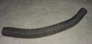 Item:
Item: Intake air pre-heat hose (from exhaust manifold shroud to air box), for Scirocco 2 (1982+)
Condition: New
$12
|
|
|
|
A2 parts for sale:
|
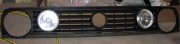 Item:
Item: GTI dual-round grille with inner lights, bulbs, and lower trim strip
Condition: Used, lower trim strip is weathered.
$35
 Item:
Item: Parcel shelf strap, 3 available
Condition: New
$3.50 ea.
 Item:
Item: 8 (eight) valve guides, German, standard size, for 8 valve head
Condition: New
$24
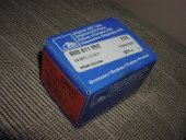 Item:
Item: Wheel cylinder (for rear drums, obviously), 2 available.
Condition: New
$12 ea.
|
|
|
|
A3 parts for sale:
|
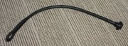 Item:
Item: Parcel shelf strap, 3 available
Condition: New
$3.50 ea.
|
|
|
|
A4 parts for sale:
|
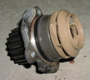 Item:
Item: OEM Water pump, ALH engines
Condition: Used, 130,000 miles
$20
|
|
|
|